
F450 crossing machine assembly and debugging(full version)
Fancy flight and long-distance artifact
F450 crossing machine assembly and debugging (full version)
Author information: Guo Yuandong, Youjiang District, Baise City, Guangxi Province, WeChat bbsgyd, the first draft was completed 2020.8.5, the revised version was completed 2022.08.01
This article provides a detailed explanation of the assembly and debugging of the F450 crossing machine. Students who like long-distance and large-wheelbase crossing machine can learn from some of the contents and easily complete the hardware assembly, parameter setting and final test flight process of the large-wheelbase crossing machine. After the first version was completed, it was released on Zhihu. Due to insufficient permissions, it was impossible to import the document. Copying and pasting only allowed text to be seen and pictures could not be uploaded. The article was loved by everyone, and the number of readings exceeded 10,000. The author had to spend some time to upload the subsequent revised version. The content was similar, but this time the editing added complete picture content, which greatly increased the recognition and integrity.
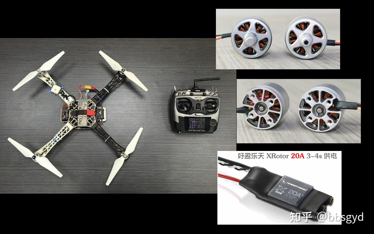
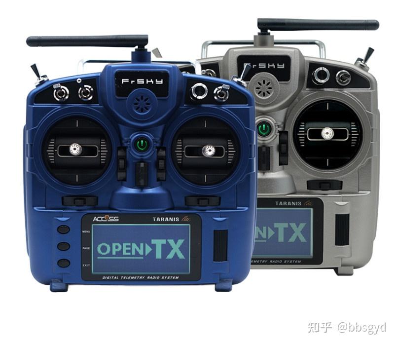
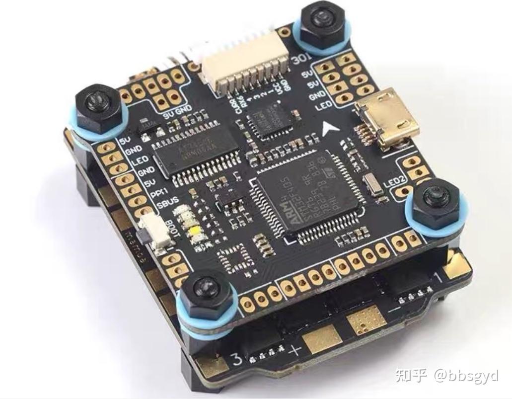
F450 quadcopter flight platform
The purpose of the F450 crossing machine
The large-wheelbase crossover can be used for visual exercises for basic introductory control of multi-rotor vehicles. The difficulty of handling is much higher than that of aerial multi-rotor aircraft; for visual control, the 5-inch crossover aircraft seems too small, and the size of the F450 aircraft is more suitable for visual control exercises. For various task mountings such as gimbals and sports cameras, the F450 rack installation space is more abundant than that of the F210-level models, and can also be used as a test flight platform.
Necessity of F450 quad-axis system
The four-axis model of multi-rotor aircraft, from 90mm wheelbase microphones to 210mm wheelbase crossing machines, to 450mm large wheelbase aircraft, and larger load-load models, the system configuration characteristics reflected by each size across the wheelbase are greatly different. The rack, power system, flight control system, remote control diagram transmission system, and mounting vehicle are all different. Among them, the F450 wheelbase scheme is the model represented by the model, with a wheelbase usually between 360 mm and 550 mm. The power unit and loading capacity are not much different, and it is a very similar model. The F450 aircraft model is usually used for aerial photography and teaching and learning, and is most widely used in personal learning and research, school multi-rotor drone teaching, aerial camera training, fancy flight performances, and aircraft scientific research. The F450 multi-rotor aircraft system is the most widely used entry-level flight platform.

F450 flight platform under test flight
The cost-effectiveness of the F450 crossing machine system
The F450 four-axis crossing machine is a very mature multi-axis aircraft solution, and the hardware it uses is a relatively cheap accessory. Among them, nylon material racks can be bought for a few dozen yuan, one set of motors costs only 100 yuan, one set of electric regulators costs about 100 yuan, one set of propellers costs more than 100 yuan, and various flight controls range from about 100 yuan to several hundred yuan. The battery packs are mostly between 100 yuan and 200 yuan. The remote control and receiver are very versatile. With a model aircraft charger, when an aircraft can fly, it costs only 1,000 yuan, which is a relatively cheap solution at the beginning stage of the multi-rotor aircraft.
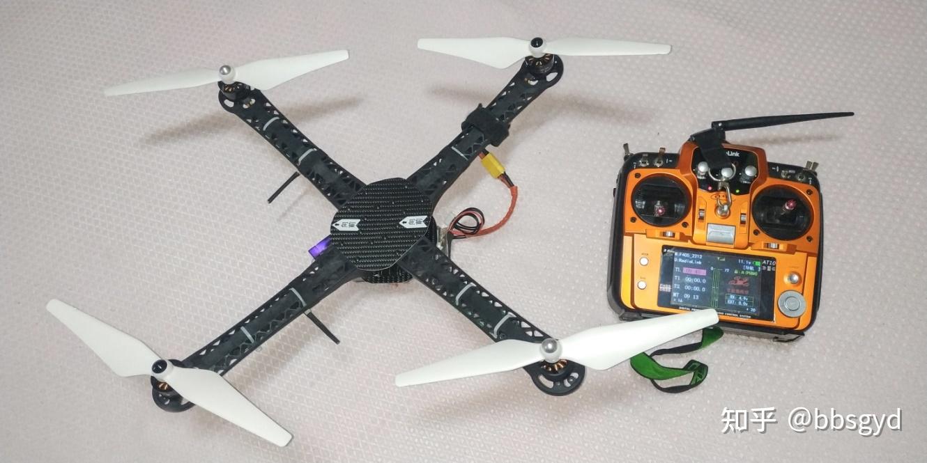
F450 flight platform assembly completion diagram
The difficulty of assembly of F450 crossing machine system
The F450 crossover assembly solution described in this article is of instructive significance for beginners’ first multi-rotor aircraft solution and assembly parameter adjustment learning. It has a low difficulty index, and is relatively difficult to implement hardware assembly, system debugging, new peripherals, and advanced functions. Beginners can easily master the assembly and debugging skills of the entire aircraft according to the stage steps of this article. However, there will be more difficulties in the flight control process. After all, flight control skills are an important part of assembly and debugging, and are also an essential basic skill for learning crossover technology. It requires more training time to complete; through the guidance of this article, the basic control skills can be easily completed.
The choice of F405 crossing aircraft flight control
For multi-rotor vehicle assembly, novices often choose DJI NAZA V1 or V2 flight control, equipped with GPS positioning receiver, and also have intelligent functions such as fixed-point hovering, low-voltage automatic return, and out-of-control automatic return. The aircraft assembled by NAZA flight control is mainly used for aerial photography flight activities, which allows operators to avoid worrying about the aircraft’s drift, loss of control, excessive power, and inconstant altitude. Users do not need to be too distracted to control the stability of the aircraft. They can devote more energy to camera shooting operations, which is very beneficial to improving the efficiency and safety of aerial photography operations.
The large-wheelbase crossover aircraft assembled in this article uses the flight control of the F405 crossover aircraft. It does not have the functions of GPS fixed-point hovering, automatic return, and fixed air pressure. The operator needs to control the throttle size at any time to achieve basic hovering. When position drifting, the joystick needs to be controlled to correct the drift. Novice will often be in a hurry and it is inevitable that it will be out of control.
What is F405? In short, it is an open source program flight controller made using the STM32F405 microcontroller processor, referred to as F4 flight control for short. In F4 flight control, Betaflight (BF) firmware program is often used, accompanied by Betaflight Configurator parameter setting software, to complete the installation and debugging of the flight control system.
The F1, CC3D, F3, and NAZE32 flight controls before F405 flight control have weaker processor performance. Parameter adjustment software usually uses the extension function of Google browser. When using these parameter adjustment software, you must first install and set up the Google Chrome before loading in the extension program, which is not very convenient to use.
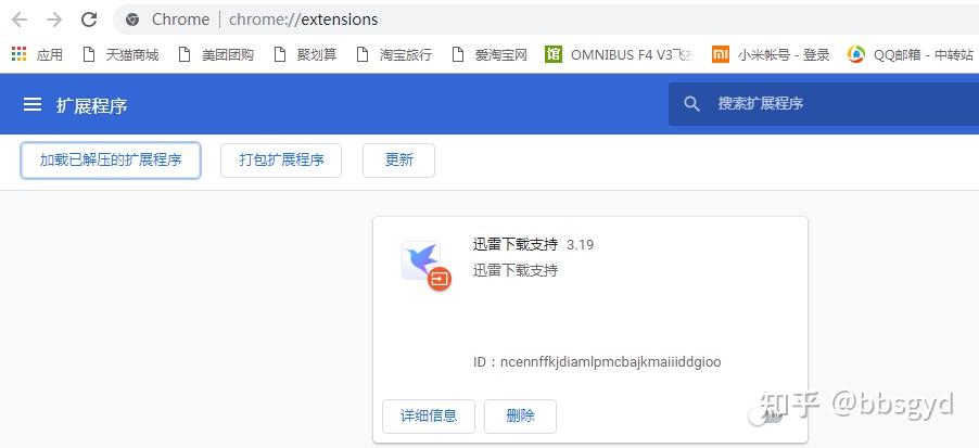
Google Chrome Extension Interface
The subsequent version of F405 flight control parameter adjustment software is installed directly on the Windows computer system and can be used independently without installing Google browser. The software supports XP, WIN7, and WIN10 operating systems. Of course, there are also programs and drivers dedicated to Apple’s MAC system, but it uses relatively more software for the WINDOWS version.
The F405 flight control uses a six-axis gyroscope for attitude comparison sampling control, which can enable the aircraft to work in self-stabilization mode, semi-self-stabilization mode and proportional manual mode. No matter which mode, there is no fixed height and positioning (fixed point automatic hover) function. The operator needs to continuously adjust and control the altitude position of the aircraft through the remote control throttle joystick at any time, and control the plane position of the aircraft by adjusting the pitch and rolling joystick of the remote control. While visualizing these operations, it also brings the operator the visual sense and sense of presence to control the aircraft, senses the changes in the attitude of the aircraft, and feels the execution of the aircraft’s rocker commands, thereby judging the impact of flight parameter settings on the aircraft’s various control intentions, improving beginners’ understanding of flight control settings software options and parameters, and also brings the operator a more on-site control sense that tends to be at will.
Why choose F4 flight control?
First, you should be prepared to encounter difficulties when heading towards multi-axis crossing aircraft, and also have the indomitable spirit. Therefore, starting with open source flight control can save a lot of twists and turns, face difficulties directly and overcome these basic problems as soon as possible, and do not need to waste time on aerial photography aircraft.
Secondly, the aircraft is larger in size, which is more suitable for visual practice, fancy flight and long-distance flight; the entire aircraft is low in cost, has strong knowledgeability, and is suitable for beginners to get started to improve; the technical information of the F4 flight control system is easy to obtain and understand, and it is easy to find experience and answers when encountering problems. Learning open source flight control applications, you are no longer fighting alone, and you face problems with young people in the intelligent electronic science world who like to mess around the world.
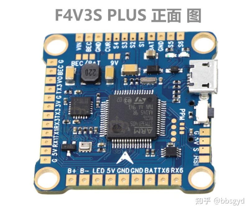
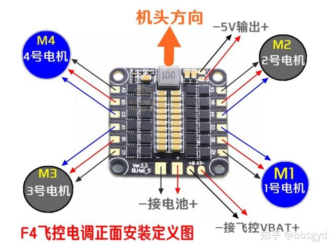
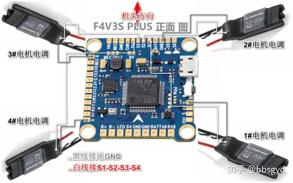
F405 V3S PLUS flight control application diagram F405 V3S PLUS flight control front view
F450 rack and power selection
The frame of the F450 flight platform is usually a nylon plastic product arm, with a resin circuit board as the center board, and the weight is usually between 250-300 grams. Choosing a rack with a reasonable design and good material is crucial for electronic device layout and installation and subsequent use durability. The 450 number indicates the distance between the ends of two oppositely mounted arms on the aircraft. The size of the frame is directly related to the length of the propeller available, thus determining the model and parameters of the motor. Usually, for the F450 rack, you can use motors with diameters of 18/20/22/23/24/26/28, such as motors of 2212, 2312, 2408, 2808 and other models; the first two digits of the motor represent the diameter of the motor 23mm, and the last two digits represent the height of the motor magnetic coil core, such as 12 represents 12mm. Use 8-10-inch-length two-blade or three-blade propellers, and match the length and pitch of the paddle according to the size of the motor and the KV value, such as the paddle marked by 9443, 9450, 1040. The first two digits of 9443 represent the length of the paddle (inch), and the last two digits represent the propulsion pitch of the paddle. For long-distance (introduction coach) machines using 2312 motors, if the budget is not very tight, it is recommended to use a carbon fiber rack, which can effectively avoid low-frequency resonance and be lighter in weight and longer in range.
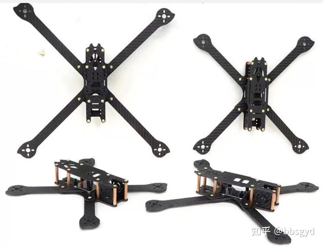
Various crossing machine racks for carbon fiber board cutting
The F450 power combination usually uses a 2312KV900 motor, equipped with a single 20A output electric regulator and 9450 propeller. The motor output shaft has its own threads, and the propeller is spiral self-tightening. During installation, it is necessary to distinguish between forward and reverse motors, and the paddles are also divided into forward and reverse rotation.
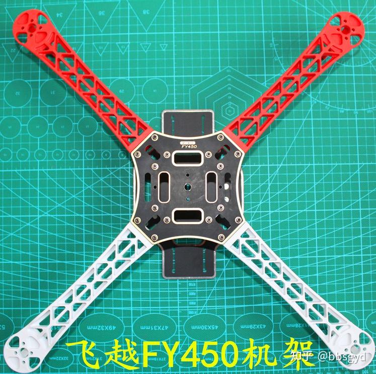
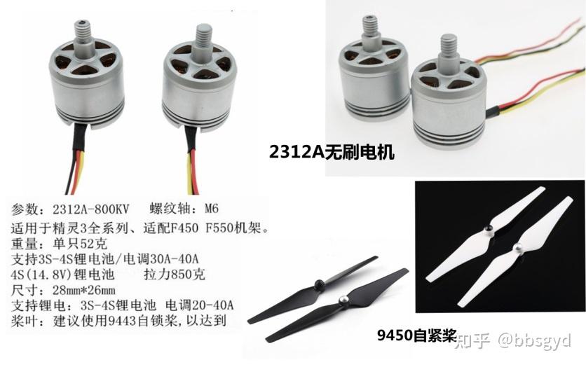
Fly over FY450 nylon frame DJI 2312A brushless motor and self-tightening propeller
The KV value of the motor is the identification of the motor speed. Motors of the same size, the paddles matched by different motor KV values are also different. For example, the 2204kV2300 motor matches the 5040 three-blade paddle, the 2312KV800 motor matches the 9450 two-blade paddle, and the 2212KV1400 motor needs to be equipped with 6050, 7040 or 8336 paddles as the optimal; when the voltage is constant, the higher the KV value, the higher the speed of the motor in every minute; if the paddle is too long and the pitch parameters are large, it will cause the motor to not reach the optimal speed, the lift generated cannot reach the optimal design value, and it will also cause the motor to generate severe heat or even burn.
The KV value is an important indicator value of the motor. When a 1V voltage is added to it, the KV1000 motor rotates 1000 revolutions per minute. When the power battery voltage is 15V, the maximum rotation speed of the motor is: 1000rX15V=15000 revolutions. This speed is the measurement data when no load is applied.
Selection of remote control and receiver
The choice of remote control is very important. When you are still in the introductory stage of multi-rotor, buy a 10-channel Fusi i6X. It is simple to set up and can store 10 model data; it is powered by a No. 5 rechargeable battery, which is easy to replace; it can choose the Chinese menu firmware, which is simple and intuitive to set up, and has outstanding cost-effectiveness. If you choose the American throttle, you won’t get back to the Chinese model. There are many types of supporting receivers. Usually we use smaller receivers, which are easy to place on the aircraft. It is recommended to use Fuss FS-W8B or FLi14+ , which is 8 channels in PPM mode and 18 channels in S.BUS mode. The reliable communication distance is more than 400 meters, perfectly matched with the remote control. If you need to install a gimbal and a caster mission vehicle, you can choose the FS-iA10B receiver to match the remote control. It is recommended to use aerial flight control of the DJI NAZA M V2 model with a PWM input socket.
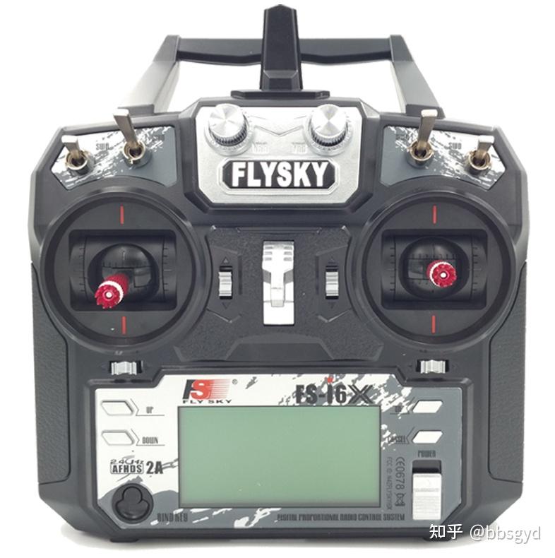
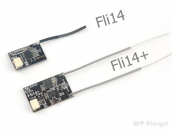
Fusi FS-i6X 10-channel remote control Fusi FLi14+ receiver

Open source remote controls for various brands
Selection of model aircraft charger
The model aircraft charger is a balanced charger dedicated to lithium batteries. Model aircraft power batteries are usually series discharge battery packs, which consist of 1/2/3/4/5/6/8/12 battery cells in series.

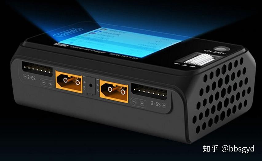
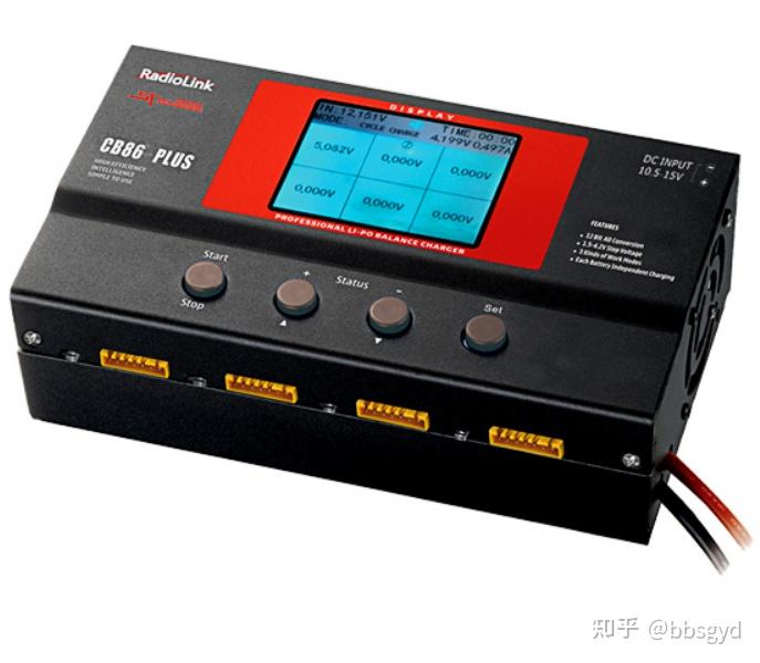
TOOLKIT RC M8, M6D dual-channel, LeDi CB86 with 8-channel nanny charger
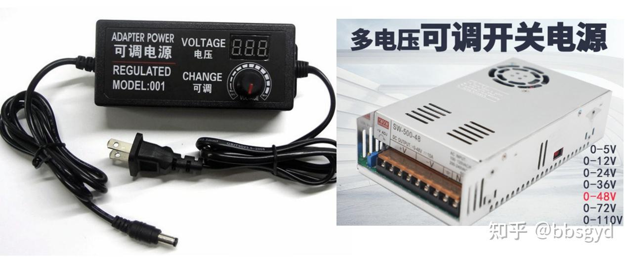
Since the charging and discharging current of lithium batteries is very large, even if the internal resistance and capacity of a single battery cell are only slightly different, overcharge damage may occur when charging in series. When charging through a single-cell balancing method, the problem of cell overcharging caused by differences in internal resistance and capacity can be eliminated. Choosing a charger with good performance and durability is what all model aircraft operators hope to do. There are countless models of model aircraft charger brands, and the performance and price difference is relatively large. Generally, choose a model with high cost performance and good feedback. Ultralarpower UP610 wide voltage input, ISDT Ester 608AC or BG-8S wide voltage input, TOOLKIT RC M8 (10-36V power supply 1S-8S), MD6 dual-channel, and LeDi CB86 (with nanny 8-channel, 11-15V power supply) are all good chargers. Among them, UP610, BG-8S, RC M8, RC M6D dual-channel, and CB86 all require another power adapter. Usually, we will purchase a 12V computer disassembly power supply to connect to these chargers and charge the battery. The power adapter is recommended to use RHT-DPS450W-36A (450SB) or HP 750W disassembly power supply. If the power supply is modified to start the output, the disassembly power supply is small in size, large in power, stable in price, and outstanding cost-effectiveness.
After purchasing the power adapter, add an XT60 plug (female) to power the charger and then charge it. For example, use the RC M8 charger to charge the 4S 1600mAh 100C model aircraft battery, and it takes only 8 minutes to complete the charging at the fastest. If you use the field electric bag assistance, you can reduce the number of flying batteries purchased.
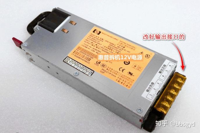
DPS-750RB A power supply 12V750W XT60 plug with cable (female)
Selection of model aircraft power battery
When choosing the power and rack scheme, we have already decided on the capacity and external dimension range of the power battery.


Whether the F450 rack uses a 3S or 4S lithium battery pack, the weight of the battery should not exceed 400 grams on aircraft using the F450 rack. The safety and redundancy of the system limits the range of battery capacity. If the forced configuration of a larger weight power battery pack will cause the system stability and reliability factors to be reduced. The takeoff weight exceeds the optimal system parameters of the design. Factors such as battery and motor overheating during flight, wind power, speed, etc. will cause the system’s flight safety factor to be reduced. For aircraft with F450 racks, the most commonly used battery packs are 3S 3300-5000mAh 35C and 4S 2200-4500mAh 35C; the battery pack is connected to the aircraft power system using an XT60 plug, and the battery pack output interface is XT60 male. If a battery configuration is used, a 4S 4000mAh 35C can allow the aircraft to fly normally for at least 20 minutes when it is no load. After indoor no load hover test, the 3S1550mAh battery can be used, and the aircraft system’s battery life can reach 18 minutes, and the normal flight during outdoor no load is more than 12 minutes.
Basic knowledge of power battery pack maintenance
The LiPro battery pack is composed of multiple cells with a nominal voltage of 3.7V in series. The discharge termination voltage of a single cell is recommended to be 3.6V and the charging cut-off voltage is 4.2V. Excessive discharge or charging exceeds the recommended voltage will damage the battery cell and will be irreversible. To protect the safety of battery discharge, an active BB buzzer can be connected to the flight control BB alarm port, and the flight control low-voltage alarm parameter is set to the average single-core voltage of 3.6V in the setting items related to the BF parameter adjustment software. When the average single-core voltage of the battery pack is less than 3.6V during the flight discharge, the battery will be immediately landed when the alarm sounds. This will also avoid the crash accident of exhausted power. For the maintenance of the battery pack, you can also use an electrical tester with a low voltage alarm to connect to the battery balance line as a low voltage alarm.
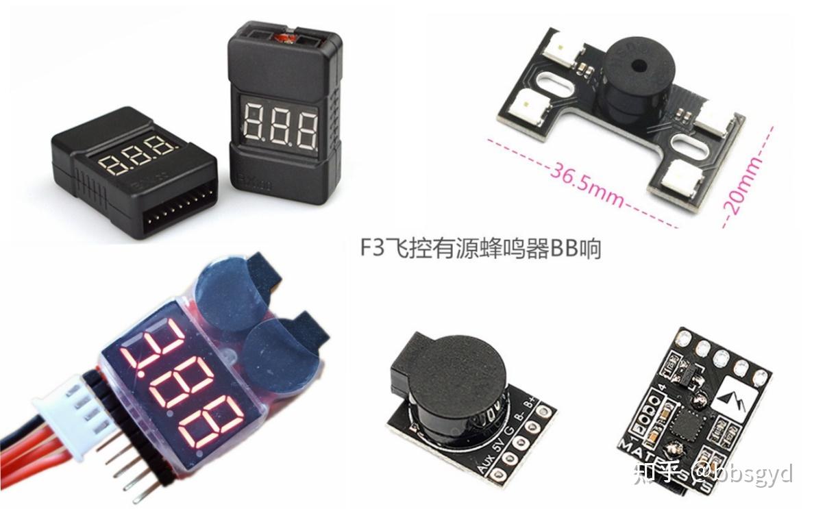
Commonly used models of active BB sounding and voltage measurement alarm
Since power lithium batteries require large current charging and discharging, some impurities mixed in the battery cell material will make the battery easily self-discharge when it is stored for a long time. The power battery pack needs to be charged as you use. After use, it needs to be charged to a single-core voltage of 3.8V before placing it. This way, the battery will not be easily placed for a long time. The ambient temperature of the battery should not be too high, usually at room temperature 5-35°C and the air humidity is below 80%. Power lithium battery packs need to be isolated and placed in an iron box to avoid fires caused by accidental short circuit or spontaneous combustion.
The discharge current of the lithium battery pack at a low temperature of 0-15°C is much smaller than that at 20-55°C. If the outdoor temperature is too low, you need to hover and discharge when you first start flying. You can only fly when the discharge current is normal before you can fly. Otherwise, the machine may fall due to large discharge voltage drop and insufficient discharge current capacity, resulting in under-powered power output. When the battery temperature exceeds 55°C, it may cause gas bulge in the battery, and the battery charge and discharge performance may be reduced or even damaged. If the power battery is deformed due to the fall of the machine, it cannot be forced to squeeze and reset, which may cause the battery to be short-circuited and caught fire.

XT60, T-plug power battery
Some tips for hardware purchase plans
The brand selection of F450 rack is very important. The quality of brands such as Flyover, DJI, and Kingkong is better; the motor usually chooses models such as 2312A, 2312, and 2212. The motor output shaft requires two positive and two reverse threads; the propeller can choose 9443 or 9450 two-blade plastic paddle; the electric control selects Haoying 20A, which supports 3-4S voltage split electric control or use four-in-one digital electric control; flight control is recommended to choose F4V3S PLUS, if you need to use NAZA V2 aerial flight control, directly purchase the entire set of accessories (NAZA flight control only supports PWM/SBUS receiver; if the remote control is selected, Fusi FS is selected. i6X and F405 flight control are recommended to choose FLi14+ receiver; the image transmission and camera can be not configured, and FPV glasses do not need to be configured. These two things can be purchased when needed in the future. In the entry stage, the first aircraft is used in the same field for basic visual control exercises, and there is no need to consider camera, image transmission and video reception glasses.
Because the aircraft is prone to damage to the bomb during the assembly and the test flight stage of the assembly, it is recommended that one or two backups be prepared in appropriate amounts; propellers are the easiest to be damaged, and you need to buy several more sets at a time; the installation of independent electrostatic control requires an electrostatic control distribution board, which divides the battery input into 4 groups to supply power to the electrostatic control.
Adjustable voltage battery charging adapter
There is no need to buy too many power batteries, 3-5 is enough. If you have plenty of time to practice outside, you can consider using a large-capacity lithium battery pack or an electric bicycle 20Ah battery as an outdoor electric bag to charge the aircraft battery. Make an XT60 plug and connect it to the battery, and the model aircraft charger can work; if you charge a 12V tram battery, you can use a power adapter with an output of 13.8V, or plan an adjustable power adapter, which is sold on major shopping platforms. Here it is recommended to find such power accessories on the Xianyu platform.
Usually, a 12V30A power adapter with MW350 watts is used. The output voltage can be fine-tuned between 10-14V. The output power is large enough, and it is sufficient for power supply and battery charging. The purchasing channel is second-hand recycling field or Xianyu online shopping. As an adapter for balanced charging and power supply for model aircraft, the output current needs to be above 15A. The current is too small and the charging speed is slow, and the adapter is prone to overcurrent protection without output.
Multi-rotor aircraft hardware assembly process
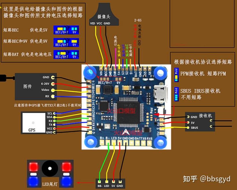
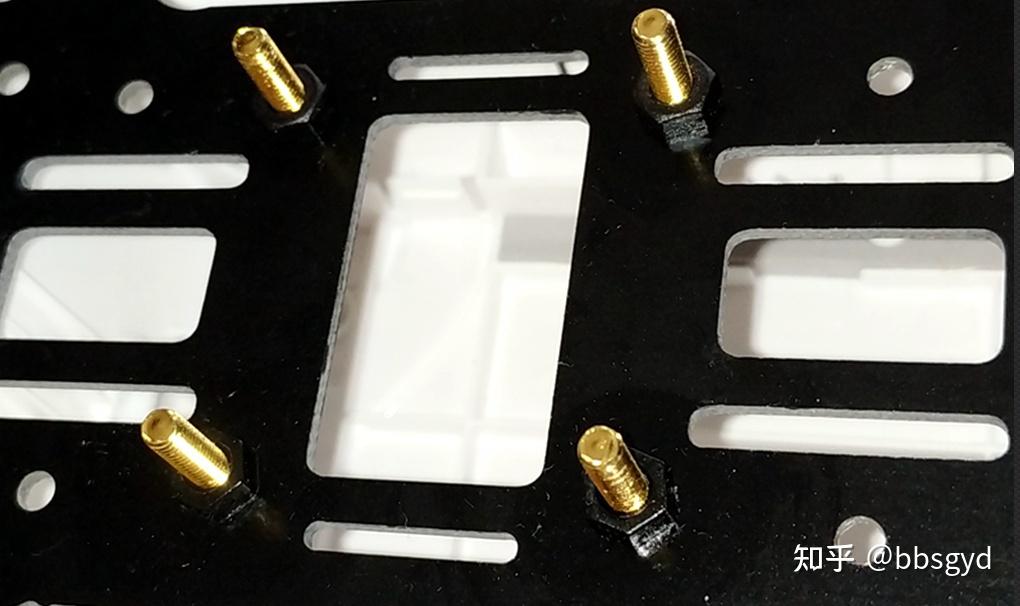
If you use the F450 frame with a plastic arm and install the F405 crossing flight control, you need to drill 4 3.5mm diameter holes in the center of the lower center plate to install the flight control screw column; the distance between the four holes is 30mm, forming a square. It should be noted here that whether there is printed circuit copper foil on the center board needs to be insulated with screws to avoid the problem of the PCB circuit board being stuck by the installation of copper columns, causing it to burn if it is powered on.
Commonly used screw specifications are M3, the diameter of the screw is 3 mm, the length is 5 mm to 30 mm, and the amount of the acetate tape or nylon binding wire is simplified. The 936 or T12 soldering iron is an indispensable tool for circuit welding. Of course, some solder wire and rosin flux are also required; screws are anti-loosening and degumming water, battery tie tie with Velcro, and the hexagonal screw batches used for screws are also necessary for hardware assembly and need to be prepared in advance.
The center plate is in the middle position of the lower plate.
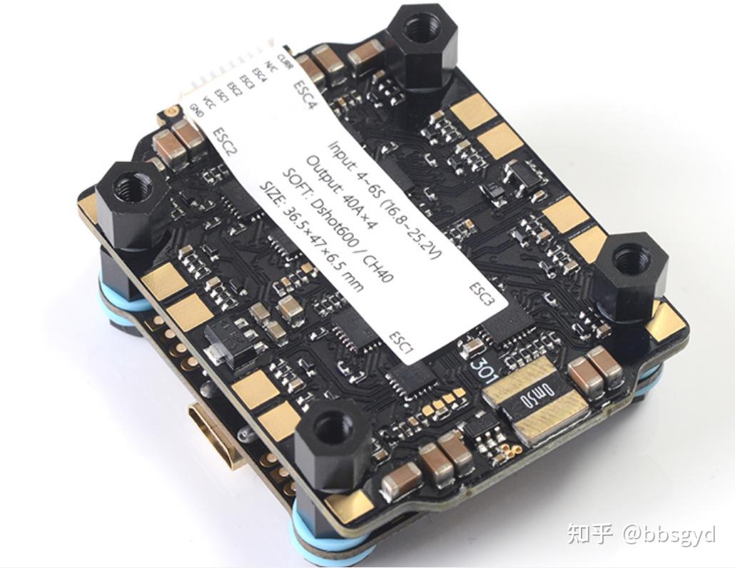
If a 2312A motor is installed using a carbon fiber rack, the installation of flight control is more convenient. Usually, on such a compact rack, F405+30A flying tower combination circuit is required. It is recommended to purchase a flying tower equipped by the same manufacturer, so there is no need to adjust the connection line sequence, which is very friendly to novices. It is recommended to use Mamba’s F405MK2+30A flight control electric-tuning combination set, with outstanding performance. Such an electronic control uses the DSHOT300 digital communication protocol, which is much easier to use than the independent electronic control of the Haoying 20A PWM protocol, and is perfectly matched with the 2312A motor.
Regarding the cooperation between DJI 2312A motor and electric regulator, the electric regulator has a single-channel 20A real output parameter that is sufficient to use. If a 30A four-in-one digital electric regulator is used, it will be more perfect. There are three models of DJI 2312/2312A/2312S. The most stable and easy-to-use one is 2312A. It is very resistant to explosion and the shaft is not easy to be crooked. In terms of explosion resistance, various motors of other 2312 models on the market. Generally, DJI 2312A models are mostly disassembly accessories, and the appearance is not very good. As long as the bearing is smooth and without abnormal noise, it can be used normally.
Install the motor
The four-axis frame needs to be equipped with a motor at the motor installation position of each arm. During installation, a small amount of screws are injected into the screw hole at the bottom of the motor to prevent loosening and degumming, so that the screws will not be loosened due to vibration during flight.
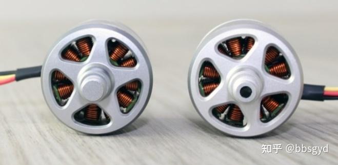
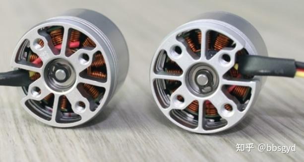
2312A motor divided into positive and negative threads 2312A motor bottom installation hole
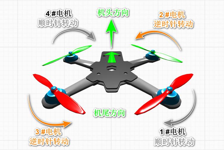
The threads on the motor output shaft on the machine arm are marked with black dots with reverse threads (the motor rotates clockwise), and are installed in the upper left and lower right direction of the head direction; the motor without black dots are positive threads (the motor rotates counterclockwise), and are installed in the upper right and lower left positions in the head direction. The position of the motor cannot be installed incorrectly, because the rotation direction of the self-tightening paddle is certain. The wrong front and back threads of the motor will cause the rotation direction of the propeller to be incorrect and the aircraft cannot take off. Please follow the following diagrams during installation. After the motor is installed, check it again.
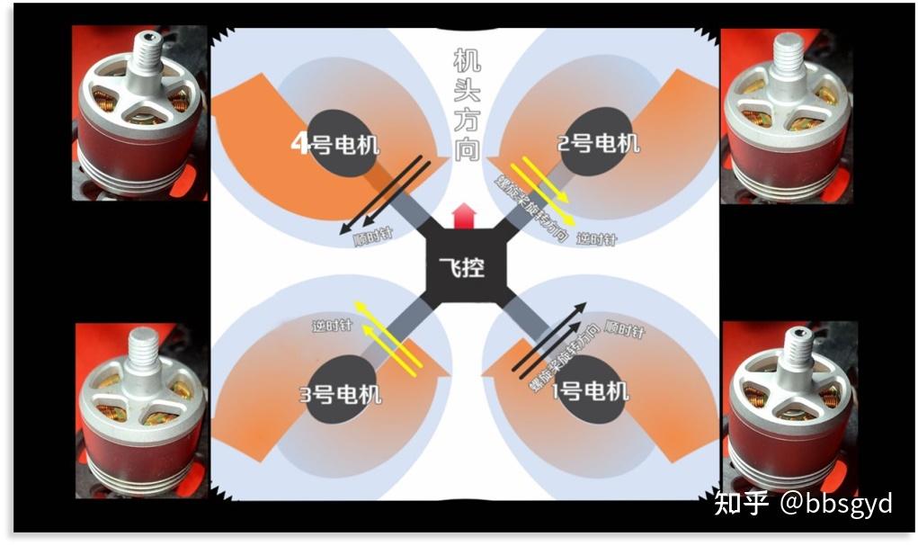
F450 rack motor installation diagram
Install the electric palette
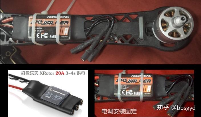
When using the F450 nylon frame, you can use a more general independent electric regulator. It is recommended to use the Haoying 20A model, which is not easy to burn the motor during start and stop. The stability and cost-effectiveness of other electric regulators are relatively inferior to that of it. It is more perfect if you use F405 flight control plus a four-in-one digital electric regulator. It is recommended to use a four-in-one digital electric regulator on a carbon fiber rack. Of course, using a high-performance cross-border independent electro-modulator is also a good solution, at least better than using the Haoying 20A Rakuten series electro-modulator that only supports the PWM electro-modulator protocol, especially when the power changes rapidly, digital electro-modulator has an absolute advantage.
Electrical installation and distribution board connection
Welding motor electro-modulation and battery interface socket
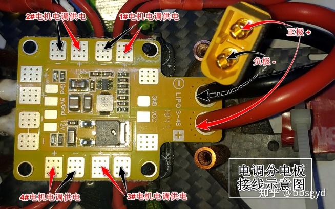
Make sure that the positive and negative electrodes have been distinguished before welding, and use red and black silicone wires to connect the distribution board and the positive and negative electrodes of the electrostatic regulator respectively. Do not connect the reverse, and the circuit will be directly burned when the wire is turned on; check the polarity again after the wire welding is completed. The 12V and 5V outputs on the distribution board are powered by the receiver (5V) and other mountings, but the maximum current does not exceed 2A. Do not connect to electronic devices with excessive power to prevent the buck circuit from burning.
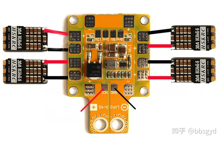
Independent electric regulator distribution board, four-in-one electrical regulator and motor wiring
The VBAT+ on the flight control needs to be connected to the positive pole of the battery input to supply power to the flight control. Do not connect this cable wrongly, as mistakes will burn the flight control circuit board.
The power battery-powered socket at the end of the aircraft is connected to the silicone wire using a TX60 male head (note the positive and negative electrodes of the socket). It is necessary to use AW12# or 10# silicone wire. If the wire diameter is too small, it will cause the wire to heat up or burn down during violent flight. When welding battery wires, you need to use a soldering iron with a power of more than 70W. It is recommended to use a T12 soldering iron horseshoe or a knife head welding nozzle for welding. Be sure to quickly and firmly solder the solder joints to the circuit board. After the welding is completed, check the welding effect and check whether there is any welding slag stick to avoid incontact or short circuit.
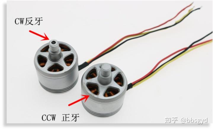
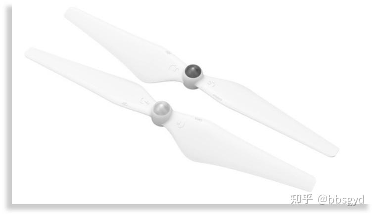
2312A forward and reverse thread motor 2312A equipped with forward and reverse self-tightening paddle
When welding the motor to connect the three wires of the electric regulator, if the input wire of the motor is not long enough, it is necessary to use wires with equivalent wire diameters for extension. The extension welding joints need to be insulated separately with a heat shrink sleeve, and then the three input wires of the motor are randomly welded to the three output welding joints of the electric regulator board. There are instructions for the adjustment of the motor rotation direction.
Connect the signal input line from flight control to electric regulator
Weld the electronic control signal lines of motor No. 1-4 with the electronic control signal output terminals of F4 flight control. The black wire is grounded. You can find any G-mark terminals on the flight control circuit board. The white wire is the electric control signal wire, which is connected to the S1-S2-S3-S4 terminals respectively. Welding precautions: The flight control is placed in the direction of the nose, distinguish the position of the electric control No. 1-2-3-4. Don’t make mistakes, and correspond to the S1-S2-S3-S4 terminals connected to the flight control. If the line sequence is wrongly welded, the aircraft will not be able to take off, which will cause the aircraft to start dancing wildly as soon as the throttle is refueled.
Schematic diagram of the electronic control signal terminal connected to F4 flight control
If the four-in-one electric control tower is used, the data cables of the flight control and electric control are allocated by the manufacturer, and they are used directly without adjustment. This is more friendly to novices who assemble the aircraft for the first time and is easier to get started. When using the Haoying Lotte 20A independent electric control, the electric control power supply is taken from the distribution board and the signal wire is drawn out from the flight control. When welding, the power supply wire needs to be soldered first, and the signal wire is soldered after the flight control board is installed.
F4 flight control connected to remote control receiver
Flight control and receiver wiring diagram
F4V3S series flight controls can support the receiver ibus/sbus/ppm signal protocol. If you use the Fuss Fli14+ receiver, this receiver only supports the iBUS protocol. The FS-i6X remote control supports this protocol and needs to be set to PPM and iBUS output. For specific remote control settings, please refer to the Fuss i6X remote control usage menu instructions. The link is as follows, “Aerospace Model” Fuss FS-i6 Model Aircraft Remote Control Setting Manual https:// zhuanlan.zhihu.com/p/53 9426622, bbsgyd’s article – Zhihu.
Power battery connected to F4 flight control power supply
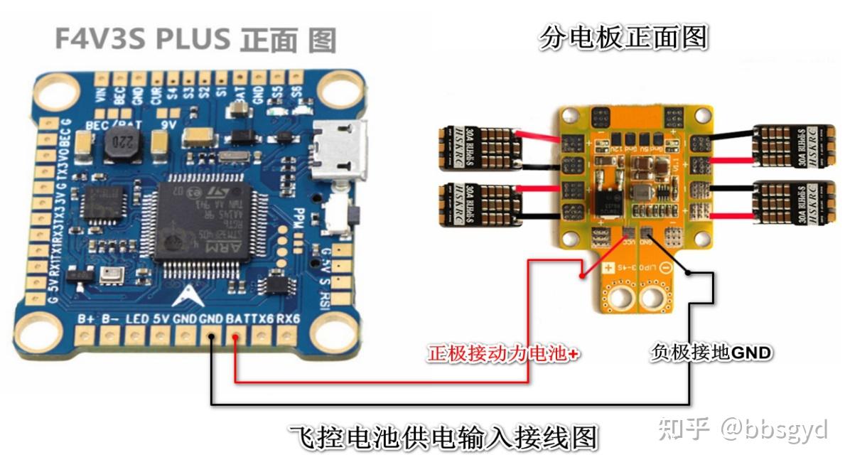
Battery connection flight control power supply connection (independent electric regulator)
If you use four-in-one digital electric control, you can directly connect the flight control with the original data cable, without the need to weld the battery power cable to the flight control’s BAT terminal. This set of power wiring is used to supply power to the flight control. The positive and negative poles must not be connected in reverse. If the reverse connection is connected, the flight control circuit will be burned. After the welding is completed, it needs to be checked again.
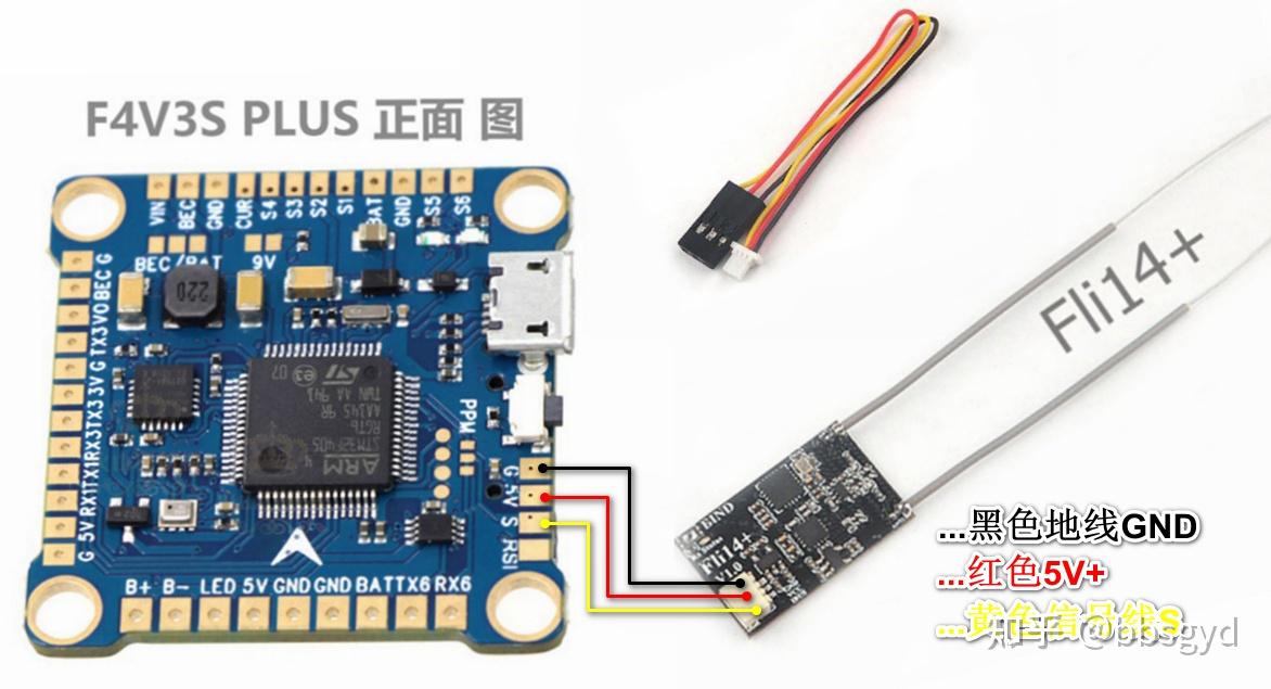
LED BB buzzer connected to F4 flight control
BB sound is a sounding device for flight control status prompts. It sends different combinations of beeps according to the instructions given by flight control in different working states to give users a prompt. LED light strips can be programmed to display different colors and flashes as system status prompts or flashes when flying, which is convenient for finding the aircraft. BB sound can also be turned on using an AUX channel in the parameter adjustment mode. When flying, buzzing and LED flashing are turned on through the remote control to facilitate identification of the aircraft’s landing point. This function is very practical, and it is meaningful to use a BB sound device with greater sound pressure.
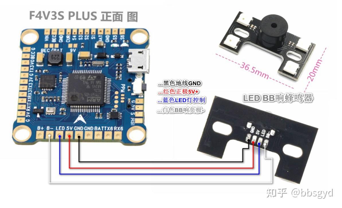
LED BB buzzer connected to F4 flight control
When connecting the two-in-one circuit of BB and LED, a 5V power supply, B-, LED, and GND ground wire needs to be connected from the flight control, as shown in the figure. The 5V mark on the flight control is the 5V power supply output from the flight control BEC secondary power supply circuit.
Camera and image transmitter are connected to F4 flight control
During the practice stage of novices, it is recommended to conduct basic flight control exercises first, without installing a camera and image transmission transmission circuit, visually control the aircraft, and then install these equipment for FPV flights.
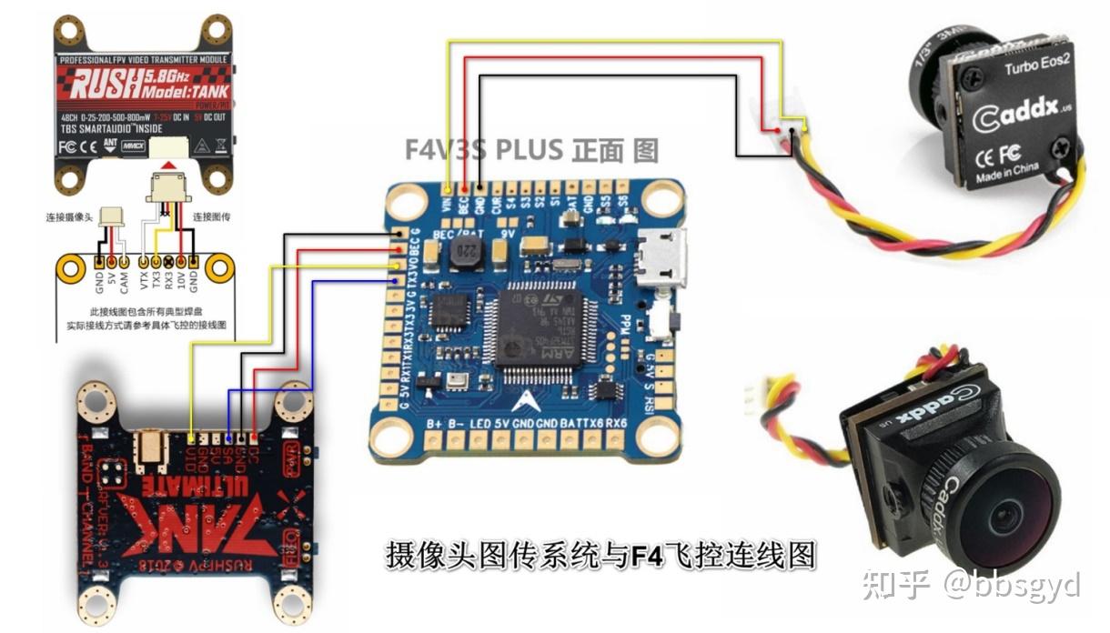
Schematic diagram of FPV camera image transmission system connecting F4 flight control
The camera needs to be connected to the F4 flight control first, and hand over the simulated AV signal to the OSD screen superposition module built-in OSD screen superposition module. The character superposition program inside will superimpose the flight parameters with the video screen, and then transmit the screen signal to the image transmission transmitter. The image transmission transmitter transmits the superimposed AV video signal through the high-frequency oscillation circuit and the radio radiation antenna. The operator receives radio signals of the same frequency through the image transmission receiver and demodulates them into video signals and displays them on the display screen. The operator controls the aircraft first-person perspective by watching the real-time picture taken by the camera in front of the aircraft, which is what people often call FPV flight. Cross-border flights usually use FPV mode, which is the most attractive part of cross-border flights.
GPS GPS receiver is connected to F4 flight control
If you need to fly the crossing plane farther, such as the distance is more than 500 meters, you need to consider the issue of flying loss. When the remote control or image transmission signal is lost, the aircraft will lose control and fly away. If a GPS global positioning system receiver is installed, set to the remote control without signal or trigger automatic return through the AUX channel of the remote control, the aircraft can fly back to the near the takeoff point by itself when it loses control to avoid flying away. GPS uses the Beitian BN-880 model module, which includes two sensors: GPS signal reception and magnetic compass (compass). After installation, calibration and related settings are performed in the ground station parameter adjustment software, it can be used for automatic return or flights on the route. Without a magnetic compass flight control, it is impossible to distinguish the direction, which means that automatic return cannot be achieved.
The other idle ports of the F405 flight control can also be connected to auxiliary functional modules such as ultrasonic range measurement, laser range measurement, and lower visual positioning to achieve accurate positioning and height setting functions. These are advanced applications after entry. When the level is improved in the future, it is not difficult to achieve.
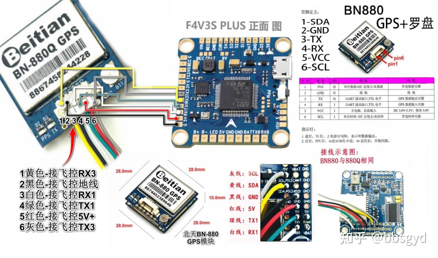
GPS, compass and F4 flight control connection
Installation and use of F4 flight control BF ground station parameter adjustment software
Install software and drivers
1. Download and install the BF software. BF is the abbreviation of Betaflight. This software can be installed on the Windows 7-10 system. After the installation is completed, a hummingbird’s shortcut icon will appear on the desktop. How to download it? This is the link address of the official website of BF , https://github.com/betaflight, The website is not from the mainland, it is a bit slow and requires a long wait time, so be patient. You can also download it in the link shared by Baidu Netdisk. Here the author shares a link, which contains various F4 flight control programs. The BF parameter adjustment software can be directly installed after downloading.
Permanent valid link: Link: https:// pan.baidu.com/s/18_4Ctg 4PlWlpOCYt-lwpVwExtraction code: v8v8. If the link is invalid, you can add the author’s WeChat bbsgyd to apply for a new sharing address.
I would like to thank the predecessors in the model aircraft industry for their selfless sharing of the experience they have explored and figured out with us through the Internet, allowing us to stand on the shoulders of giants and continue to move forward, saving a lot of time for exploration; when I can master a new application based on my predecessors, I will immediately take action to summarize and record, and share it with those in need through the Internet; thanks to this sharing era, we will make progress faster!

QR code link extraction and file preview
If you need STM32F405 flight control new version of the universal firmware link is (technical connection may be required): https://github.com/betaflight/b etaflight/releasesThe latest version of firmware release page.
When connecting the parameter adjustment software for flight control, the device driver needs to be installed in advance. Before installing the driver, you need to download the CP210x_Universal_Windows_Driver.zip, stm32102.zip and zadig-2.4.exe files. The first two files are normal online drivers, and the latter one is the DFU mode driver for firmware, and the driver is also downloaded in the network disk address above.
The driver installation is divided into parameter-adjusting serial port COM driver (connecting flight control with USB cable) and DFU driver for brushing firmware in BOOT mode. Zadig driver is a dedicated driver for turning on the DFU connection.
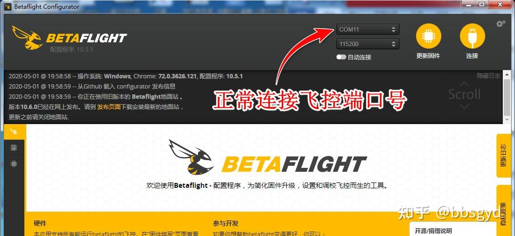
Normal online parameter adjustment mode COM port status
The corresponding port situation can be seen in the computer’s hardware manager. The device with the name STMicroelectronics Virtual COM Port (COMxx) appears in normal online parameter adjustment mode; and the STM32 BOOTLOADER device appears after installing the Zadig driver is used for flashing firmware mode.
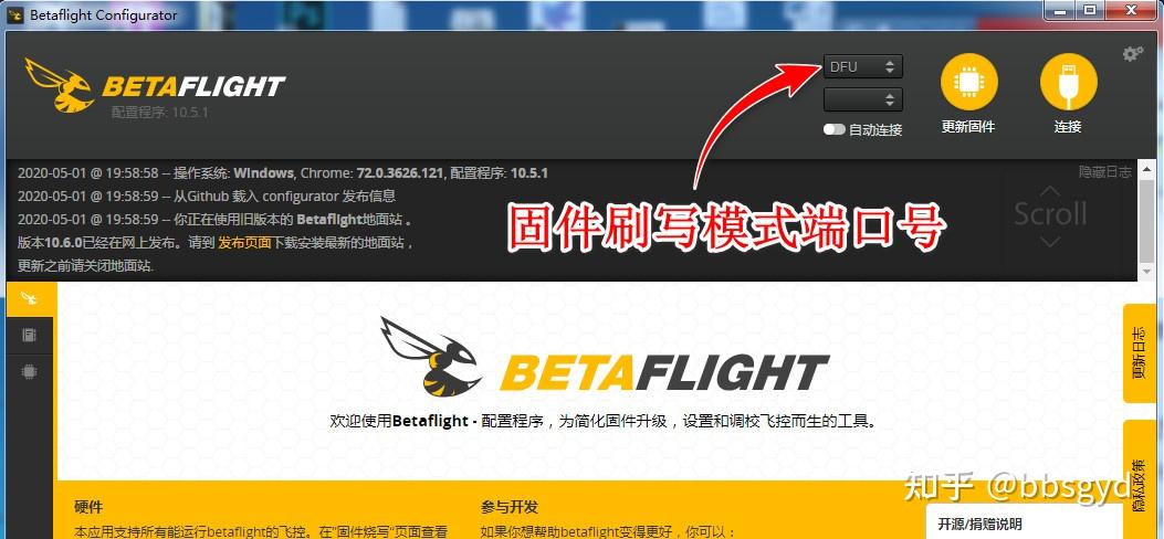
DFU online port status in BOOT mode
First, install the COM driver in normal parameter adjustment mode. If the driver cannot be installed during the installation process, the STMicroelectronics Virtual COM Port (COMxx) device does not appear or cannot be used. You can install a driver wizard to help you install the missing system files and this driver. It is very simple to solve the problem of not installing the driver. At the same time, it is recommended to install and debug in 64-bit systems above Windows 7.
If you need to update the firmware, you need to install the driver in the firmware update mode. Press and hold the flight control BOOT button and then connect the flight control to power on the USB data cable. The flight control enters the BOOT mode. The computer system will find a new device and enter the device manager to install the driver for the new device. You can use ZADIG software to automatically install the driver or download the STM32 BOOTLOADER folder in the driver folder shared by the network disk, and install the DFU port driver by specifying the path. After the BOOT mode driver is installed, start the parameter adjustment software again, and a DFU firmware update device port will be captured.
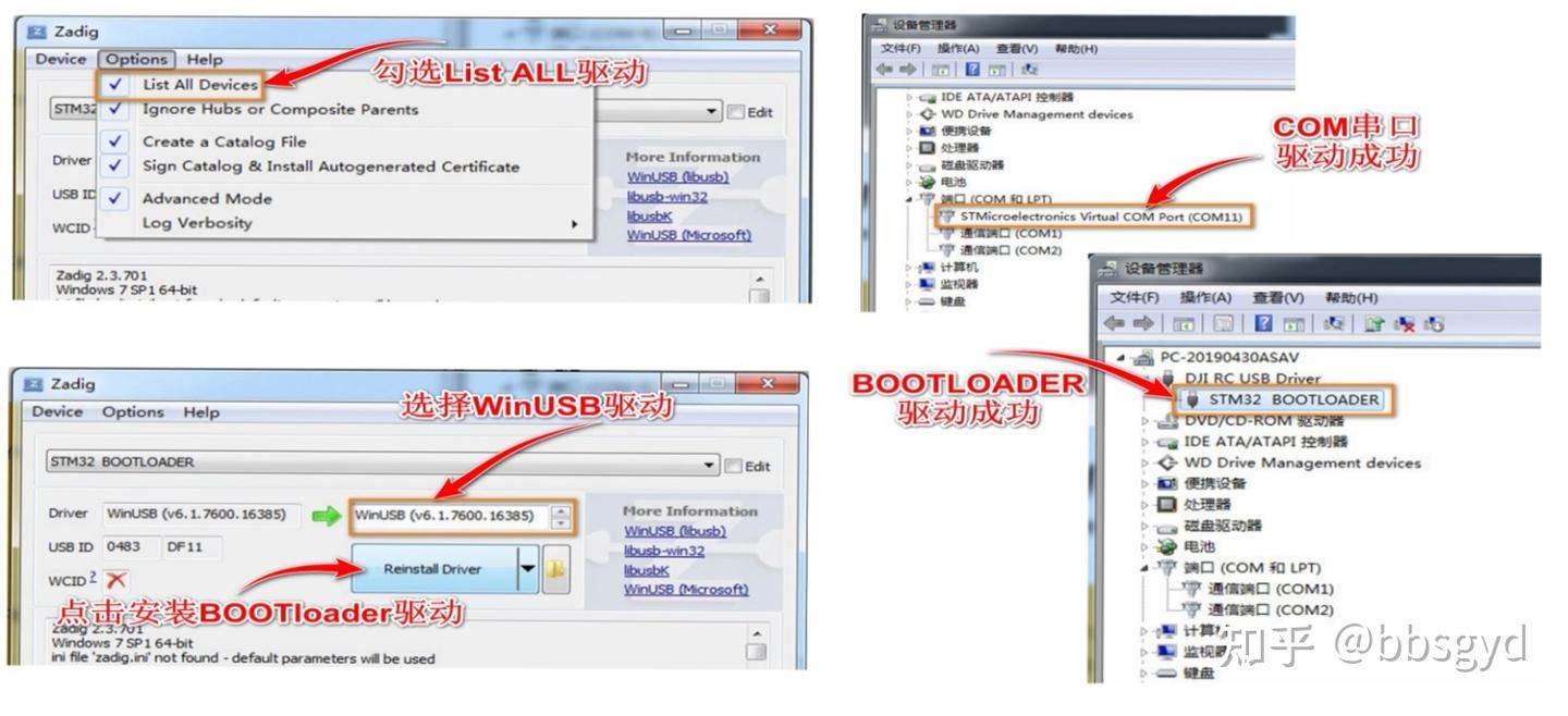
Installation diagram of COM serial port and BOOT mode UDF driver
Start BF ground station to connect to the aircraft to update the firmware (novice can skip this section)
The key to updating the BF parameter adjustment software is to install the DFU mode driver, and the DFU port appears is a success.
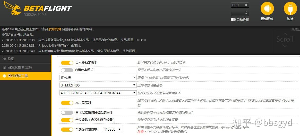
BF parameter adjustment software firmware writing tool interface
Press the BOOT mode button on the flight control and connect to the USB data cable to observe that the indicator light on the flight control board is always on. This is the computer discovered new hardware and installed the driver automatically. You can see a STM32 BOOTLOADER device in the computer’s device manager; a DFU port was captured on the BF parameter adjustment software. At this time, click the “Update Firmware” button on the BF software and wait a lot of time. When the firmware writing tool interface is displayed, open the “Show non-stable version” switch, open the “No need to restart” switch, open the “Full disk erase” switch, and open the “Manual Set Baud Rate 115200” switch; then click “Load Firmware from Local Computer” in the lower right corner and select the already downloaded BF firmware (do not flash CF firmware on the BF software, the flight control may lose contact).
Firmware is the fixed operating system software of flight control, which is responsible for managing and applying flight control hardware resources; brushing firmware is to reinstall an updated or older version of the operating system program for flight control; firmware erasing is to clear the original flight control operating system program; burning is to erase and write the new flight control operating system program.
When you first come into contact with flight control, many nouns are very unfamiliar. Scholars need to spend more time understanding these special nouns and learn them based on this as a basic knowledge base to achieve twice the result with half the effort.
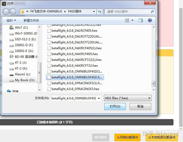
Select the flight control firmware program to be written
After loading the firmware, click “Firstware” to start erasing the memory and writing to the firmware program. The flight control will automatically restart after completion. After the flight control is connected again, the flight control will automatically enter parameter adjustment mode. After the port is captured as COMxx, click the “Connect” button in the upper right corner of the BF parameter adjustment software to enter the parameter adjustment interface.
F4 flight control parameter setting interface
If you select a non-standard matching firmware when selecting a firmware, the “Calibration Accelerometer” button on this interface is gray, or the receiver and other peripherals cannot be connected, it is because the input and output interface definition of flight control and the port interrupt settings are inconsistent. At this time, you only need to download the Config configuration file provided by the flight control manufacturer, enter the command in the CLI (command line) interface of the BF parameter adjustment software and enter, and SAVE enter save and restart. If the Config configuration file is correct, all ports and hardware are corresponding one by one, and then the flight control parameter debugging is carried out.
The official website link URL of related resources https://github.com/betaflight/b etaflight-configurator/releases/tag/10.7.2, this is the latest ground station software version 10.7.2 of F405 flight control. This is the last version that supports Win7 system. The subsequent 10.8.0 needs to be installed under the Win10 system, and the flight control must be flashed with 4.3.0 firmware.
Configs configuration command URL https://github.com/betaflight/u nicked -targets/tree/master/configs/defaultAfter refreshing the CONFIGS configuration file code page, select the .config file according to the Flight Control brand and model, right-click the file name of the corresponding Flight Control model, open it in a new window, you can see the command line, copy it all to a new text file to save it for later use.
https://github.com/betaflight/b etaflight/releases/download/4.2.11/ betaflight_4.2.11_STM32F405.hexIt is the firmware of BF4.2.11 version. If you have set up the flight control, please remember to backup the settings. After flashing the firmware, you can restore your original settings.
Configs configures copy and input command line
If you are not sure whether you can find a Configs configuration command line file that conforms to the flight control hardware design, then before refreshing the firmware, you need to save the current hardware configuration data of the flight control in one go. The specific operation is to enter the CLI command line window of the ground station, enter the DUMP command to enter, and copy all the command lines that appear to be in a newly created text file for backup. After you finish writing the firmware, use these command lines to restore the hardware configuration of the flight control. The operation is to enter the CLI window of the parameter adjustment software, copy the command lines just now, paste them in the input bar and press Enter, enter SAVE after completion, save the flight control after the flight control will restart, connect the parameter adjustment software again, and the flight control hardware has been configured.
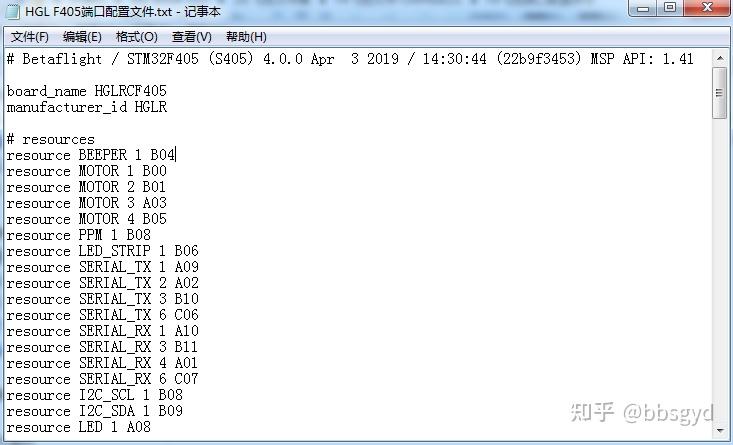
HGLRC F405 flight control Config configuration command line file
Open the corresponding version of the Configs file downloaded, copy all the command lines, and use it in the “CLI Command Line” interface of the BF interface to complete the basic input and output configuration of flight control’s hardware.
If the Config command configuration file used does not correspond to the brand model of the refreshed firmware, the correct port may not be opened, and various devices will not be connected. The corresponding configuration file should be downloaded when downloading the firmware.
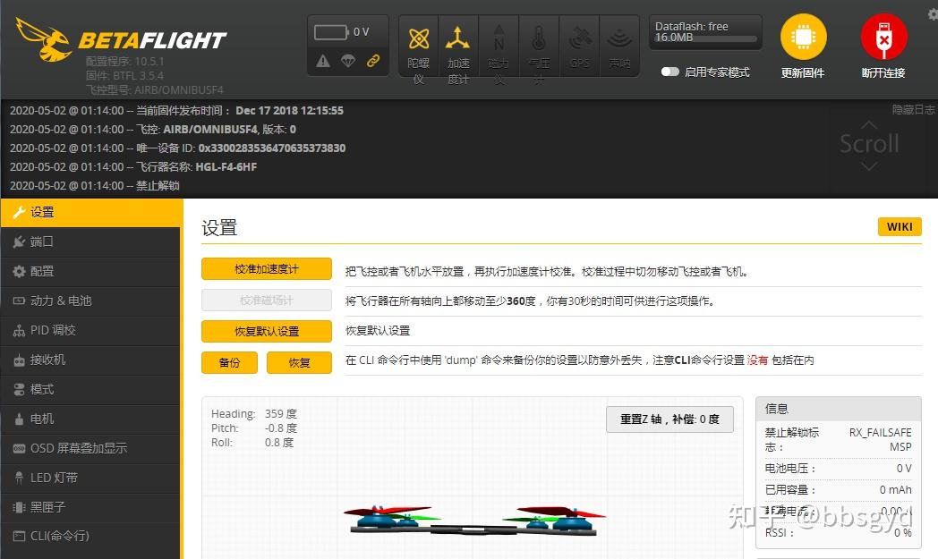
F4 flight control connects to BF ground station to adjust parameters
On the connection interface of the ground station parameter adjustment software, when you see the port COMxx appear (installed in front of the flight control driver), click the “Connect” button to enter the F4 flight control parameter adjustment page and start setting various parameters of the flight control.
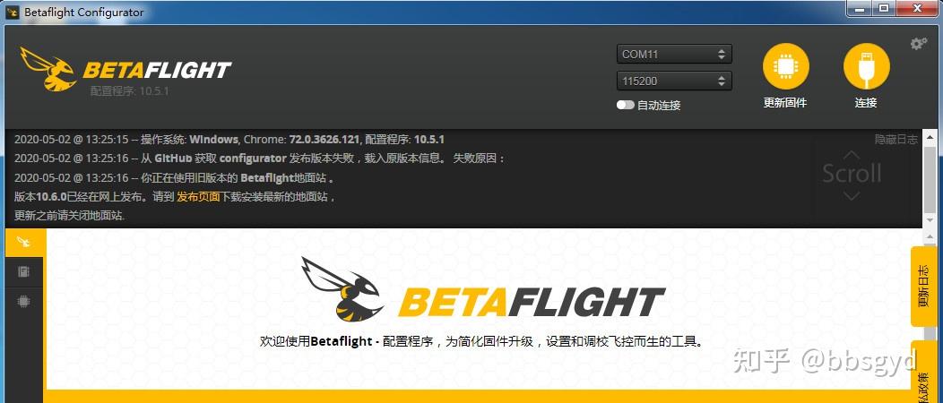
BF ground station parameter adjustment software startup interface
Flight control initialization settings
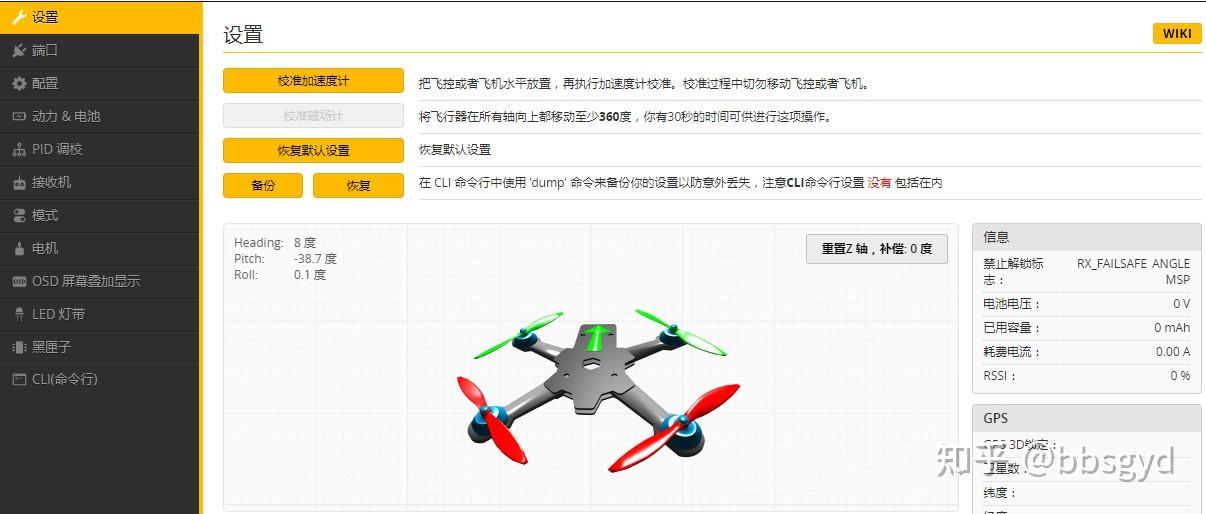
Enter the BF parameter adjustment interface, and click “Restore Default Settings” once under the settings page. This operation will restore the variable parameter settings inside the flight control to a default initial state. All parameter modifications made to the flight control have been reset. The flight control needs to reset the parameters, and the original backup data can also be restored to set the parameters.
Then let the plane sit horizontally and click “Calibrate Accelerometer” once. At this time, the program will calibrate the gyroscope accelerometer in a horizontal standstill state. This reference parameter will have an impact on future flights. Flying in self-stabilizing and semi-self-stabilizing modes, the horizontal reference of the aircraft in pitch and rolling axial directions is related to this. Because the gyroscope is shaken and its own accuracy image may also cause the aircraft to experience horizontal tilt drift; when flying in proportional manual mode, because the horizontal reference reference comparison of the gyroscope is not performed, the horizontal tilt phenomenon will not occur under ideal conditions.
BF parameter setting page
The backup button is used to save the settings after the parameter adjustment is finished. These parameters will generate a file. Different aircraft and different setting parameters can be well managed by customizing the file name.
The recovery button restores the corresponding configuration item parameters through the settings data file saved earlier, without reconfiguring these parameters again. Because the original setting values entered through the CLI command line cannot be backed up during backup, if necessary, these special setting values must be configured again through the CLI command line window.
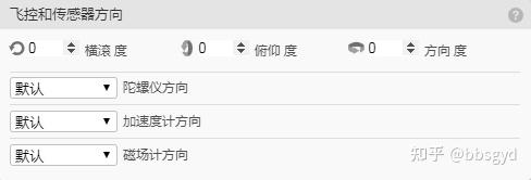
The aircraft posture diagram seen on this page shows that the pitch, roll and heading postures will change in the direction when turning the aircraft. Here we need to determine whether all attitude directions correspond.
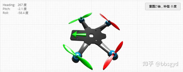
Aircraft attitude observation model
If the pitch, roll and heading of the above model are inconsistent, you need to enter the flight control and sensor direction bar of the “Configuration” page to set it. By selecting different accelerometer installation direction angle data, correct the installation angle difference, save and restart and observe the model again until the posture of this model is consistent with the actual change direction of the aircraft. This setting is crucial, and it will enable the gyroscope sensor to determine the correct head orientation so that the multi-rotor aircraft can take off correctly. If the setting is wrong, the model is inconsistent with the attitude changes of the aircraft, and a rash attempt to take off will lead to a serious accident.
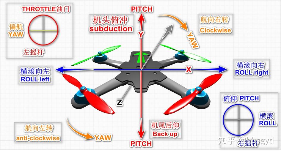
Popularize the above terms: pitch, roll, and heading .
Pitch means dive and backward PITCH. The aircraft tilts to the nose and tail directions based on the horizontal state, and the horizontal position of the aircraft changes to the front and rear of the tail of the aircraft. The aircraft moves forward and backward in the nose direction.
Roll ROLL, also known as rolling, means that the aircraft tilts horizontally to the left and right in the direction of the nose, the aircraft horizontally changes to the left and right of the nose, the aircraft moves to the left and right, and the aircraft rolls around 360°.
Heading YAW, also known as the head direction, when the aircraft is stationary or moving, changing the head direction is to change the head angle; the head rotates around the Z-axis direction for one round, and the heading angle changes by 360°.
Quadcopter attitude and orientation display diagram
Self-steady flight mode: The aircraft locks at a maximum tilt angle. No matter how large the pitch and rolling rocker offsets, the horizontal tilt angle of the aircraft will not be greater than the set value. This is suitable for beginners’ practice stages.
Semi-Stable Flight Mode: The pitch and rolling offset rod amount is greater than the set value, such as 75%, the aircraft will intend to make continuous angle changes, no longer force the horizontal posture to maintain a horizontal posture, and the aircraft will perform rolling actions. When the aircraft rolls more than 270°, the forced attitude water setting will pull the aircraft to a horizontal state. This mode is also often used in non-proportional angle rolling exercises (semi-Stable Mode rolling), which is usually used in advanced flight control exercises.
Proportional manual flight mode: the pitch and rolling attitude offset of the aircraft are all manually controlled; the aircraft changes the tilt angle according to the remote control joystick command, and the aircraft will move towards the tilt direction. When the power continues to remain unchanged, the aircraft will drop in height due to gravity, so at this time, the throttle lever should be appropriately supplemented to increase the lift to overcome gravity. The control in this mode is similar to the principle of the direction of driving control of the car. After tilting, it is necessary to return to level and then move the joystick in the opposite direction. The appropriate lever can bring the aircraft back to level and increase the throttle to maintain height.
Motor rotation direction test
After checking that the F4 flight control and the electric control signal and battery are connected correctly, open the motor interface of the F4 flight control and parameter software, follow the prompts and adjust the position of the three power cables of the motor and the electric control to let the motor rotate direction as shown below.
Schematic diagram of the rotation direction of the Quad X layout motor for quadcopter
Operation steps: Remove the propeller and connect the power battery to the aircraft; On the motor page of the BF parameter adjustment software, open the “I already understand the risks…” switch at the bottom, then slide the “Main Control” slide bar up to about 1050, so that all four motors start to rotate at low speed, and observe whether it meets the rotation direction of the above figure; if it does not meet, mark it, and then switch the position of the power line of any two motors connected to the electric control to rotate the motor in the opposite direction, so that it meets the rotation direction shown in the above figure; the motor is incorrectly turned, the aircraft will not be able to take off.
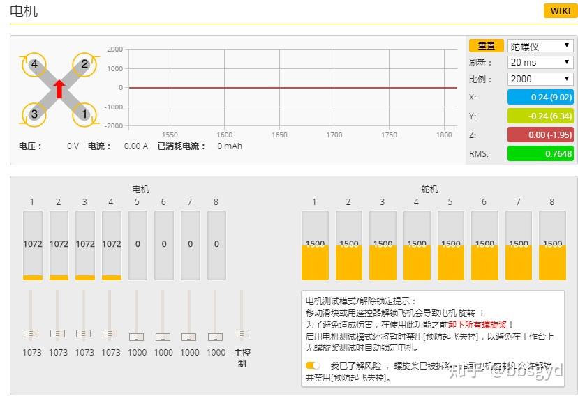
BF parameter adjustment software motor rotation test page
The settings on this page can also be used for the electrostatic throttle stroke calibration under the PWM signal protocol. When the electric control’s electric control signal output is PWM option, then, before use, the electric control needs to perform a stroke calibration of 0-100% of the throttle value. The variables from the minimum to maximum stroke of the remote control’s throttle are simulated through the lowest and highest “main control” slider, so that the electric control can remember the minimum signal and maximum signal value of the electric control command output by the electric control.
The operation steps are: 1. Connect the flight control with a USB cable. At this time, the battery powered plug needs to be disconnected; 2. Turn on the “I already understand the risk…” switch at the bottom of the motor page; 3. Pull the “Main Control” slide bar to the highest position; 4. Connect the power battery at this time. When you hear the motor ringing a few times (Didi, DiDi-), pull the “Main Control” slide bar to the lowest; 5. After hearing the motor ringing a few times, turn off the “I already understand the risk…” switch; 6. Disconnect the power supply line between the aircraft and the battery, and the electric throttle calibration is completed.
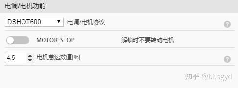
If the electric pallet used supports digital signal protocol, the DSHOT150-600 protocol is selected on the configuration page “Motor/Electronic Control Function”, and there is no need to perform electrostatic throttle stroke calibration; the four-in-one electric pallet of the crossing machine almost supports the DSHOT protocol, and this type of electric regulator is often used in 210 wheelbase crossing machines that require faster response.
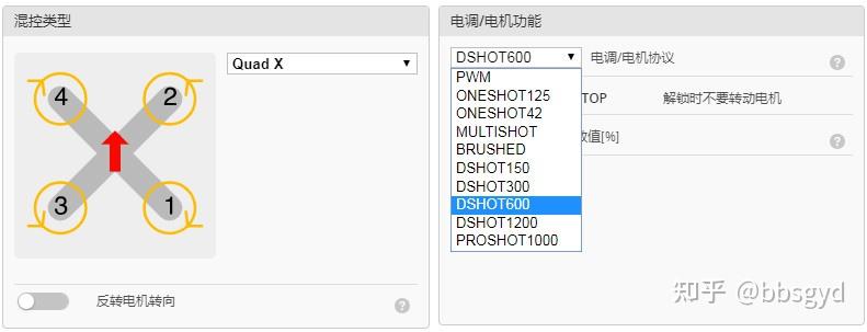
Flight control motor/electrocontrol function protocol settings
Notes:
When using PWM, Oneshot125, 42, MULTISHOT, and BRUSHED electric regulation protocols, the minimum throttle (the lowest throttle value of the flight control output to the electric regulation when unlocked) needs to be set to higher than the lowest value of the remote control throttle joystick, such as 1100; the maximum throttle value (the maximum value of the flight control sent to the electric regulation) should be set to lower than the maximum value of the remote control throttle joystick, such as 1900, otherwise the motor cannot be unlocked for flight. There is no need to set it here under the DSHOT protocol.
Flight control minimum and maximum effective throttle parameter setting bar
Flight control receiver port settings
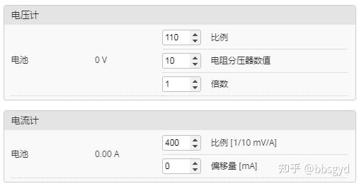
Configure the serial port and receiver mode (serial/ppm/pwm) as needed. The receiver manufacturer has good frequency control, set the channel mapping, and configure the minimum maximum value range of the channel so that they can cover 1000 to 2000. Set the median value (default 1500), fine-tune the three channels of the remote control AER to 1500, configure the rocker dead zone, confirm the receiver’s behavior when the remote control is turned off or out of range (out of control protection). Setting details are in the Receiver section. Important tips: Read the document’s out-of-control protection stamp before flight and configure the out-of-control protection.
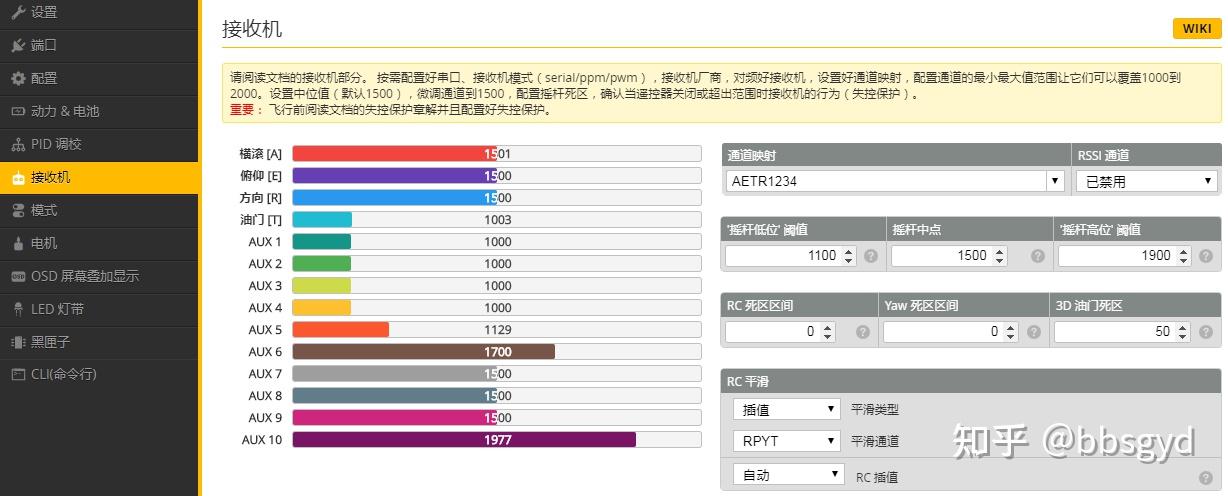
Flight control receiver rocker parameter configuration page
Key points: The median value of the remote control rocker (middle point of the rocker) determines whether the aircraft is stable and whether it is off-limited when hovering. This value is different according to different remote controls and receivers. Some receivers may not be 1500. You need to observe the AERT rod value numerical column in the middle, and adjust the median value of the three AER rockers on the remote control with the fine-tuning button to be consistent. The low and high gate values of the joystick are for the minimum and maximum pulse width of the remote control joystick. Usually, the pulse width is between 1000 and 2000. The value that needs to be set here must be between the rocker pulse width value, not less than 1000, nor greater than 2000. It is generally recommended to set it to 1100 and 1900. If the low and high gate values are set incorrectly, the motor will not be unlocked.
Flight control port settings page
Tip on the parameter adjustment page: Not all combinations are valid. If the flight control checks that a combination cannot work at the same time, the settings of the corresponding serial port will be reset. Note: Never turn off the MSP option of the first serial port, otherwise you may have to re-bury the firmware and clear (lost) all settings. This is the port connected to the computer, and turning it off will be troublesome.
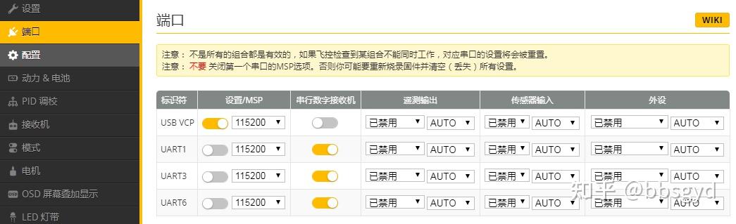
F4 flight control port settings page
Some flight control default receiver ports are usually hidden and not in the list. Generally, we can use the receiver port without setting them. The UART port is like the external expansion port of a computer, which can connect many functional devices. Regarding the use of UART ports, new students need to know more about the various application knowledge of flight control and peripherals to be used well.
Settings of flight control parameter configuration page
Tip: Not all functions can be enabled at the same time. When the flight control detects a conflict, the corresponding function will be disabled. Note: Please set the serial port to enable correctly on the port page, and then enable the function that requires the serial port.
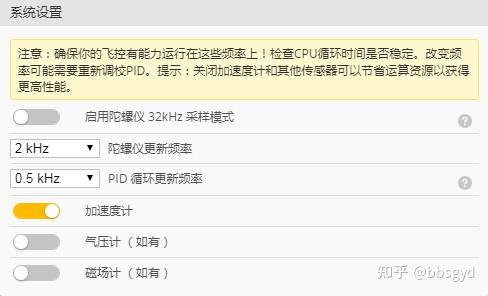
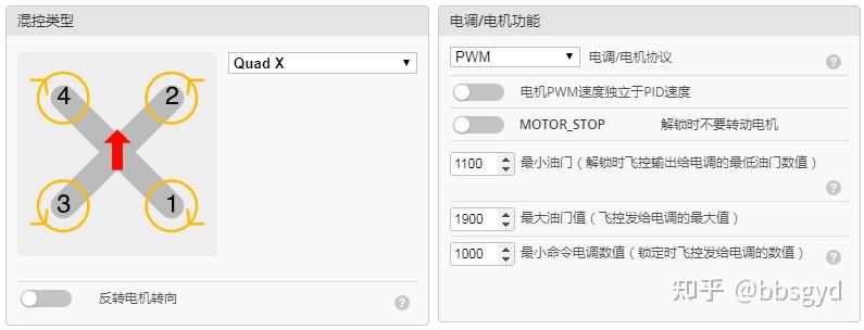
Mixed control type setting system sets the gyroscope sampling rate
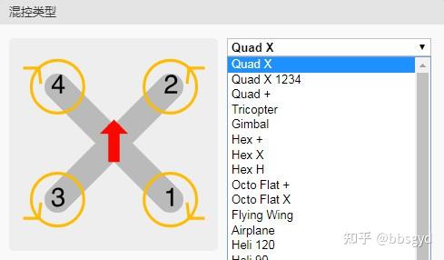
The hybrid control type is the power layout mode of the aircraft. Quad X type layout is usually used. Pay attention to the corresponding motor definition number and motor rotation direction. The motor rotation direction is based on the type.
The system settings are mainly to turn on the accelerometer, set the gyroscope update frequency and PID cycle update frequency. The larger the value selected here, the higher the sampling rate, and the more delicate and sensitive the aircraft’s movements are. For aircraft with large wheelbases, using a lower gyroscope update frequency will make the flight movement more stable and smoother and save power.
Motor electro-control function settings flight control and sensor direction settings
The electromechanical function of the electromechanical control has been explained in detail before, and different protocols are selected for the electromechanical control.
The flight control and sensor direction settings are related to whether the aircraft can fly. In the flight control initialization section, the content about the aircraft’s attitude is introduced. If the attitude orientation of the actual shaking of the aircraft and the movement of the model on the parameter-tuning attitude observation interface is inconsistent, the accelerometer installation angle difference parameter is selected here, save and restart, and then go to the observation interface to observe the model’s attitude orientation changes until the model’s attitude and the aircraft’s attitude change are completely corresponding.
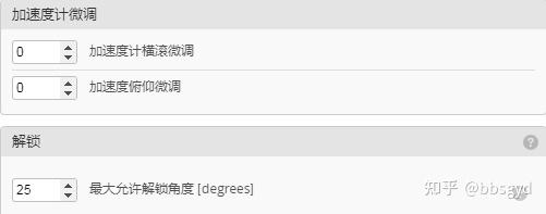
Accelerometer fine-tuning personalized settings
Accelerometer fine-tuning can only adjust the fixed drift of roll and pitch. If you find that the aircraft’s horizontal attitude always deviates in one direction, you can try to adjust it by presetting an expected value parameter here. Roll fine adjustment: Positive number is the horizontal angle adjustment to the left, negative number is the horizontal angle adjustment to the right; pitch fine adjustment: Positive number is the horizontal angle adjustment to the dive direction, and negative number is the horizontal angle adjustment to the backward direction.
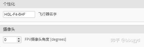
In the personalized settings , you can give the aircraft a name, and you can add numbers in English to facilitate the identification of settings when saving the settings and exporting the file. This function may not be applicable.
The camera angle is usually not required during the visual practice stage, and is set when FPV flight; this parameter can be set to 15-25°, which can enhance the aircraft’s cornering control feel during FPV flight, and cannot be felt during visual practice.
Receiver parameters set the signal strength of the RSSI receiver
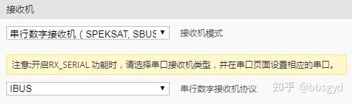
The serial digital receiver mode can be used in the receiver settings , and the IBUS protocol is selected for the Fuss FLI14+ receiver. The settings of the receiver, remote control, flight control receiver mode, and flight control receiver port need to be integrated into four parts, otherwise the flight control cannot perform signal recognition. Even if the flight control receiver port is correctly opened, it will prompt that the receiver signal is not detected. Many new students are stuck in this link and cannot solve the problem for a long time.
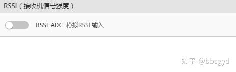
The signal strength setting of the RSSI receiver is to transmit the remote control transmit signal strength value instantly received by the receiver to the remote control through the receiver’s return channel, telling the operator that the remote control transmit signal strength value received by the aircraft at this time is used as a reference for whether to continue flying far. Generally, there is no need to set it here, because the FLI14+ receiver has no back-pass RSSI input interface. If you need to apply the modified function, you can choose a receiver such as FS-X6B.
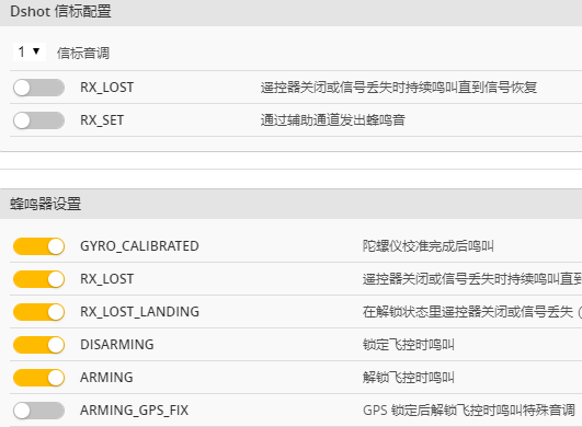
Other functions to set DSHOT beacon and buzzer configuration
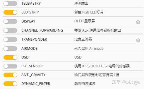
The LED_STRIP color RGB LED strip is turned on in the other function settings bar, and other options as shown in the figure can also be turned on; beacon configuration usually does not need to be turned on; the buzzer settings can be turned on. If GPS is not applicable, all items related to GPS are turned off. Key tips: If AIRMODE mode is enabled permanently, the plane may bounce down in self-stabilization mode. If you are used to the feel of this mode, you can turn it off; the SOD character overlay function must be turned on in FPV; if you need to learn to set the filter function of flight control, dynamic notch filtering can be turned on, and several dynamic filter options will appear in the filter bar under the PID page.
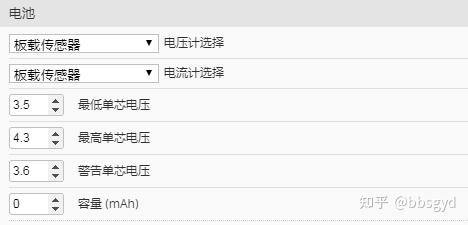
Power battery settings voltage and amp meter settings
The power battery settings usually set the minimum single-core voltage (alarm) value at 3.5V. After the flight control detects that the average single-core voltage of the battery is lower than the set value, it will issue a continuous emergency alarm sound through the buzzer; the maximum single-core voltage is set at 4.30V, which means 4.30 x N=total voltage (because the flight control can only detect the total power battery voltage, but cannot detect the single-chip battery voltage separately. The single-core voltage such as 17.20V/4=4.3V is calculated proportionally by the total voltage. At this time, the aircraft regards the battery pack as 4 batteries with a single-core voltage of 4.3V in series; the warning single-core voltage is set at 3.6V. After the flight control detects that the average single-core voltage of the battery is lower than the set value, it will issue a short alarm sound through the buzzer, prompting the pilot to land immediately to replace the battery. This setting is to remind the operator that the battery voltage is low and the power is about to be exhausted. It will land in time to stop discharge, so as to avoid battery damage and machine crashes due to power exhaustion.
The settings of voltage and amperometers do not need to be changed unless the total voltage deviation given by the sensor is too large.
Receiver settings
On the receiver settings page, if the three links of remote control, receiver, and flight control receiver options are correctly set, you can see the rod quantity data of each channel of the remote control received by the receiver; the values displayed here of the roll A, pitch E, direction R, throttle T, AUX1, and AUX2 are the real-time parameters transmitted by the current remote control; the median values of the rocker in the three observations of roll A, pitch E, and direction R need to be consistent. If they are not the same, it is difficult for the aircraft to control. You can adjust them through the channel fine-tuning button on the remote control to make them all display as 1500 values or other consistent rocker median values.
Receiver parameter setting page
There is another important parameter that needs to be set here, which depends on whether the motor can be unlocked.
The low-level gate value of the rocker needs to be set to be 50 higher than the lowest value among the three observation terms: roll, pitch, and direction. If the lowest value is observed to be 1000, it needs to be set to 1050.
The midpoint of the rocker is 1502 we just saw. If this value does not correspond, the aircraft will be difficult to control, which is manifested as the aircraft will always drift and twist in all directions, just like a soft water pipe spraying water on the ground.
The same is true for the high-position gate value of the rocker. The value needs to be set to 50 lower than the highest rod quantity. If the maximum rod quantity is observed to be 1980, it needs to be set to 1930.
The minimum and maximum gate value are set outside the observed minimum and maximum lever quantity range, the motor cannot be unlocked. When the unlock switch is turned, the buzzer will be heard to remind the remote control that the lever quantity exceeds the minimum and maximum values of the rocker, and the motor is not unlocked.
Remote Control Settings
The setting of the remote control is also a crucial link. Only by setting the flight control to receive the receiver signal.
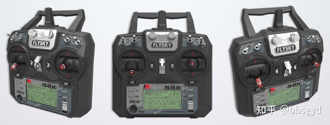
Fusi FLYSKY FS-i6X Ten-channel Remote Control
Setting and understanding the menu function of remote control is an essential basic skill for model aircraft scholars. Beginners who are poor in remote control knowledge need to spend more time learning about remote control settings. The remote control setting capability is related to the level of aircraft adjustment and measurement, which is an integral part of the comprehensive capabilities of aircraft scholars.
The settings menu of the Fusi FS-i6X remote control is relatively simple, with six switch buttons on the panel:
1. POWER is the power switch; OK is confirmation (long press, short press).
2. CANCEL is for saving or returning (press for 2 seconds to save the settings, press for a short time to return).
3. UP is upward; DOWN is downward.
4. BEND KEY frequency matching is the receiver frequency matching mode. Press and hold this button and turn on the remote control power to enter RX Binding.. Wait for the receiver to power on and automatically adjust the frequency. Before the receiver is powered on, you need to hold the frequency matching key. After the frequency matching is completed, turn off the remote control and turn on again. The receiver indicator should always be on.
Model settings for remote control
After the remote control is turned on, press the OK key for 2 seconds before entering the menu MENU. There are two icons inside, one SYSTEM “System” and the other SETUP “Settings”.
Select system settings
Press the ok key for a short time. Common items that need to be set under the system are:
1. Under Model select model selection, short press the OK key to enter the selection model Model 01. FS-i6X can store 20 different model data. Press the CANCEL key for 2 seconds to save the settings and automatically return to the previous menu.
2. Under the Model name model name, select different English and numbers to give the 01 model a name for easy memory. Finally, press the CANCEL key for 2 seconds to save the settings.
3. Under the Type select type selection, the four-axis default to Airplane or glider aircraft or glider.
4. Under the Model copy copy model, a new aircraft model can be quickly established by copying a set of model data. After the receiver frequency is checked, the same type of model can be used directly.
5. Under the Model reset reset model, reset the model data, and all parameters need to be reset.
6. Under the RX setup reception setting, turn OFF to ON in AFHDS 2A and turn on the protocol mode; under the PPM output PPM output, turn OFF to ON, turn on the PPM output mode, and OFF matches the PWM mode receiver; under the i-BUS Setup IBUS settings, set to CH1, and use 1 channel as the IBUS protocol channel.
7. In sticks mode, select Mode2, which is the layout of the left-hand throttle US hand stick.
8. Under Factory reset factory settings, all model parameters and receiver settings will be lost.
Other items do not need to be set. If you want to know the functions of other items that have not been explained, you can specifically learn relevant information about the remote control menu function. Fuss official website address https://www. flysky-cn.com/.
STUP settings of remote control
Press the OK key for a short time and the items that need to be set under SETUP:
1. Under the reverse channel flip, you can flip the channel, all of which are NOR.
2. Under the Een points channel range, setting the high and low range of the channel usually does not need to be changed, but if you use the PWM protocol to connect the servo or gimbal, you need to adjust the range of this parameter to adapt to peripheral control.
3. Under Display display, you can observe the real-time bar volume change value diagram of all channels. If the corresponding switches of the AUX channel have been set, you can see their changes when you toggle the switches here; Important tip: If you hold the CANCEL button for 2 seconds in this interface, you will enter the channel bar volume self-test mode, and all channel bar volumes will automatically change from the median to the highest and then to the lowest. If the aircraft is still unlocked at this time, it is dangerous! The aircraft suddenly increases the accelerator and spirals to escape. It is uncontrollable. Never turn on the channel self-test when the aircraft is powered on.
4. Under the Aux channels auxiliary channel, set a two-speed switch on 5 channels, such as 5-channel SWD switch, 6-channel SWC switch, 7-channel SWA switch, 8-channel SWB switch, 9-channel VRA knob, and 10-channel VRB knob. After setting, press the CANCEL key for 2 seconds to save and return. The 5-channel SWD two-speed switch will be used in the BF parameter adjustment to unlock the flight control motor, and the 6-channel SWC three-speed switch is used to switch flight mode.
5. Fine-tune the neutral point in Subtrim. If the neutral point of a remote control is too deviated, you can adjust it here to make the neutral point of the 1/2/3/4 channel reach the same value.
5. Under the Dual rate/exp dual-rate ratio, if you don’t understand, please do not make adjustments.
6. Under the Throttle Curve throttle curve, if you don’t understand, please do not adjust it. It can prevent the amount of rocker in the throttle stroke from changing according to the average proportion. Adjusting it can increase or decrease the throttle volume earlier.
7. Under Mix hybrid control, multi-rotor aircraft does not need to set hybrid control, the default value is.
8. Under the Elevon lifting aileron, multi-rotor aircraft does not need to set ailerons, the default parameters are enough.
9. Under the V tail V-shaped tail, multi-rotor aircraft does not need to set a tail wing, the default parameters are enough.
10. Under the Switches assigns switch, multi-rotor aircraft does not need to be set, the default parameters are enough.
11. Under the Throttle hole throttle plate, multi-rotor aircraft does not need to be set, the default parameters are enough.
12. Fuss FS-i6X modify the number of channels, enter the SYSTEM system settings – AUX SWITCHEN switch channel under the English menu, modify 6 to 10 at the CH below, and press and hold the CANCEL button on the panel for 2 seconds to save the settings. If the remote control appears after resetting, only 6 channels are displayed, the number of channels needs to be modified.
The above Fusi FS-i6X remote control needs to be set up and paid attention to have been explained in detail. If you need to know other aspects of the remote control, you can find relevant knowledge points on the Internet to accumulate and learn continuously.
Remote control is an important part of model aircraft, and most scholars will have multiple remote controls. The functions of remote controls of different brands and different prices are the same, the difference is the size of the transmit power and the length of the communication distance, or the reliability of 0.1%. A scholar who has just approached the world of model aircraft usually does not have experience in model aircraft and has no concept of remote controls. However, no matter what grade or performance the remote control is purchased, they must choose big brands, because their products are highly reliable, more reasonable in design, and fewer problems in subsequent use, and usually do not waste too much time on the remote control.
Commonly used remote control brands include: FLYSKY, LeDi Radiolink, Futaba, Tiandifei WFLY, Micro, Huakol DEVO, DJI, Jumper open source, Radiomaster open source, etc.
Flight control mode settings
Let’s first understand the functions of several commonly used mode range settings, and then start setting them.
The ARM motor is unlocked . After the two-speed switch is turned on, the motor is in an unlocked state, and the motor starts to rotate at idle speed.
ANGLE posture self-stabilization mode , low sensitivity and locked in tilt angle, used for practice in the introductory stage of novices.
HORIZONG posture semi-automatic mode , with a high sensitivity; within a certain angle, if it is less than 30°, it is ANGLE mode, and when it is greater than 30°, it is ACRO mode, this limit is not a mutation, but a gradient. The specific parameters are set in PID Tuning Tab – Angle/Horizon – Angle Limit, and you can use it in simple rolling exercises.
Manual mode is proportional to manual mode, and does not appear in the mode switch. When the set three-speed switch is in non-ANGLE and HORIZONG modes, it is in manual mode, which is the pulse width range of 1700-2100. This mode aircraft is in a state of no horizontal self-steady. After any change in pitch and roll angle, it needs to return to the horizontal posture and then hit the rod in the opposite direction. It may take several corrections to return to the ideal state. Beginners must use it with caution.
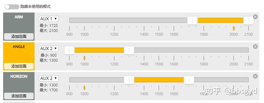
Mode page settings ARM unlock, ANGLE self-stabilization, HORIZON semi-stabilization flight mode switch
The yellow interval is the switch gear is in an active state, the gray area is the invalid area, drag the slider to define one area, and the other function mode switch settings are shown below.
Other function mode switch settings
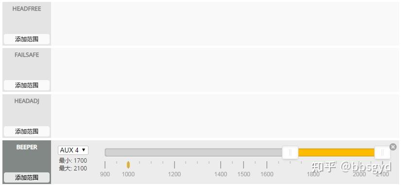
Headfree headless mode, regardless of the direction of the head steering, the direction of the head when it is turned on shall prevail.
Failsafe is out of control, set a switch to perform flight setting actions set by the out of control interface when it is out of control.
Headadj re-specifies the direction of headless mode, and it is recommended not to use it in FPV flight.
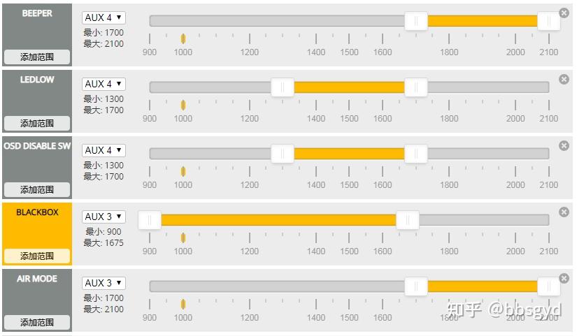
Beeper buzzer, set a switch, which is turned on when you need to find the plane, and the alarm will make a sound.
Other function mode switch settings
Ledlow LED external light strip, set a switch to turn it on or off, it is also OK to turn it on normally.
Osd sw OSD locks, and uses a switch to make text appear or turn off text on the OSD screen.
Blackbox flight recorder, black box, if the switch is not set, the aircraft will be recorded when unlocking.
Air mode In air mode, the motor keeps turning when the throttle is received, that is, the throttle PID is still working in the air, and the aircraft can still be controlled, which increases the aircraft’s air stagnation ability. Especially when doing rolling action, the actual effect is like your four-axis losing gravity and floating in the air. It can be superimposed on any flight mode, self-stabilizing and semi-steady. The fully manual + AIRMODE + SUPER EXPO or RATE combination can better play the characteristics and functions of freestyle flight, usually open in all three flight modes.
FPV ANGLE MIX FPV perspective angles can be turned on when flying FPV, compensating for rolling and heading horizontal attitudes.
Blackbox Erase Blackbox Erase, set an erase switch to erase the contents of the flight recorder on the flight control and start recording again. Usually, the recorder has a limited capacity and can only record flight data for a few minutes.
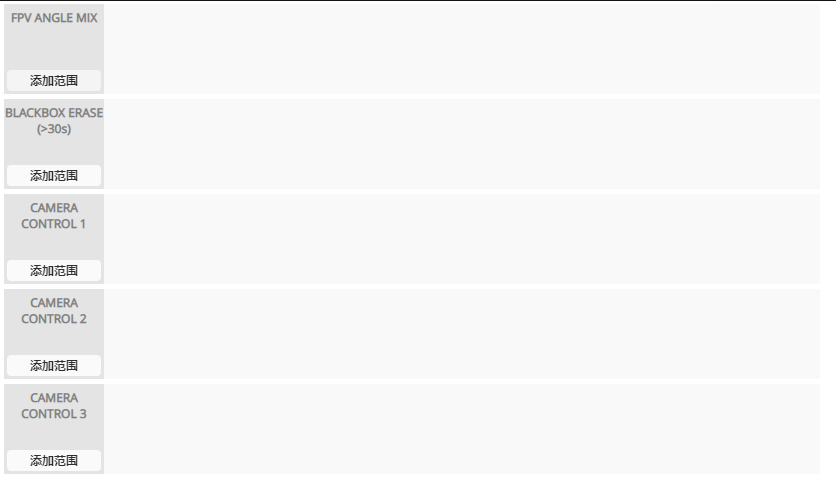
Camera control1 camera controller 1, use knob or switch to control camera shooting start and stop.
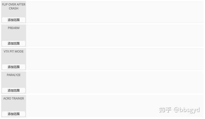
FLIP OVER AFTER CRASH suddenly flipped, in the turtle mode, the motor rotated in reverse, and it needed two-way electric control support to use it. There was no need to pick up the bomber, and many people were using it.
Prearm pre-unlocks, the motor unlocks the cut-off, and it will be turned on before it can be turned on.
VTX PIT MODE graph transmission low power mode, controls the power value through a data line to the graph transmission board.
Paralyze paralysis mode is a very practical function. After the bomb is turned on, the plane cannot be unlocked and the power is cut back and restored.
ACRO TRAINER angle limit mode, used when novices practice.
Other possible mode setting instructions
Turn assist motor brakes, the motor does not rotate inertia when reeling the throttle, and uses the reverse braking function.
Heading hold is maintained, and the heading is locked. You can turn on the test and experience it yourself.
Nav alternative height is maintained, and the atmospheric pressure value is measured by a barometer, and the height remains unchanged.
Surface level, with sea level as the reference level.
Nav poshold fixed point flight mode.
Nav rth satellite navigation return mode.
Nav wp navigation mode.
Home reset repositions the return point.
Gcs nav comprehensive distribution.
GPS RESCUE GPS rescue mode, when enabled, when the switch is turned off, the GPS rescue mode is activated.
TELEMETRY turns back data on or off (also known as telemetry data).
The mode used in the introductory practice stage of the RATE mode.
LAUNCH CONTROL takes off with one click, and the aircraft takes off when the throttle is set.
ANTI-GRAVITY anti-gravity mode, a flight PID mechanism. When the throttle value changes rapidly, it can reduce sudden pitch drops, and compensate for a little when the throttle changes are large. Usually by increasing the gain of the I term, the I term will remain unchanged during the rest of the flight. This function needs to be configured in Configuration before it appears in ModeTab.
Killswitch self-destruct.
GTUNE parameter adjustment.
AMG starts the compass lock tail.
BARO air pressure is set to high.
NAV LAUNCH is hand throwing mode.
OSD screen display data settings
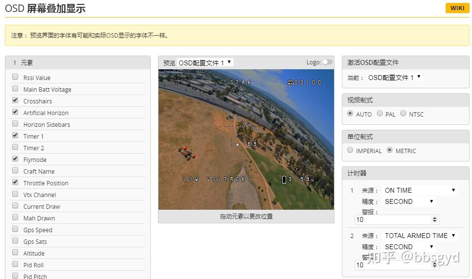
Usually, the displayed data include single-core voltage, battery low voltage alarm, throttle value, flight time, flight mode, horizon, etc. Too many screens are not good to watch.
LED light strip settings
The F4 flight control’s BB sound two-in-one light strip can be set through the CLI command line, and the general commands are as follows:
LED taillight command line, press Enter every line input.
# led
led 0 0,15::CTONIW:3
led 1 0,14::CTONIW:3
led 2 0,13::CTONIW:3
led 3 15,15::CTONIW:3
Finally, enter Save to save and write to the flight control’s EEPROM. The flight control automatically restarts the command to take effect.
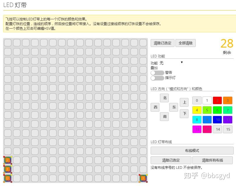
If the above command line cannot correctly set the LED light to turn on, you can use the wiring mode to set the LEDs and other colors through this graphical interface programming interface.
Black box settings
The F4 flight control without an SD card slot will come with a 16-megapixel memory that can store several minutes of high-sampling rate flight data. If a large-capacity recorder is needed, you can install a flight recorder through the flight control external port, or use a flight control with an SD card slot, and install a 4GB memory card into the flight control TF card slot. If the memory card is too large, it will generally not be used up all the space.
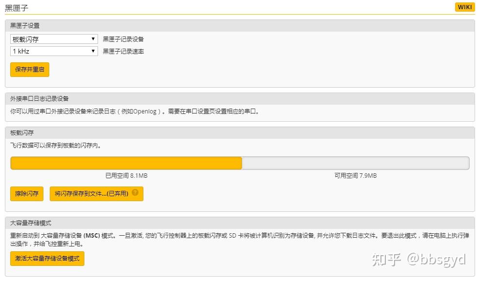
The flight control version without a built-in SD memory card will have built-in 16 mega flash memory
The F4FV3 flight control standard version all comes with an SD card slot, which can be inserted into a 4GB memory card.
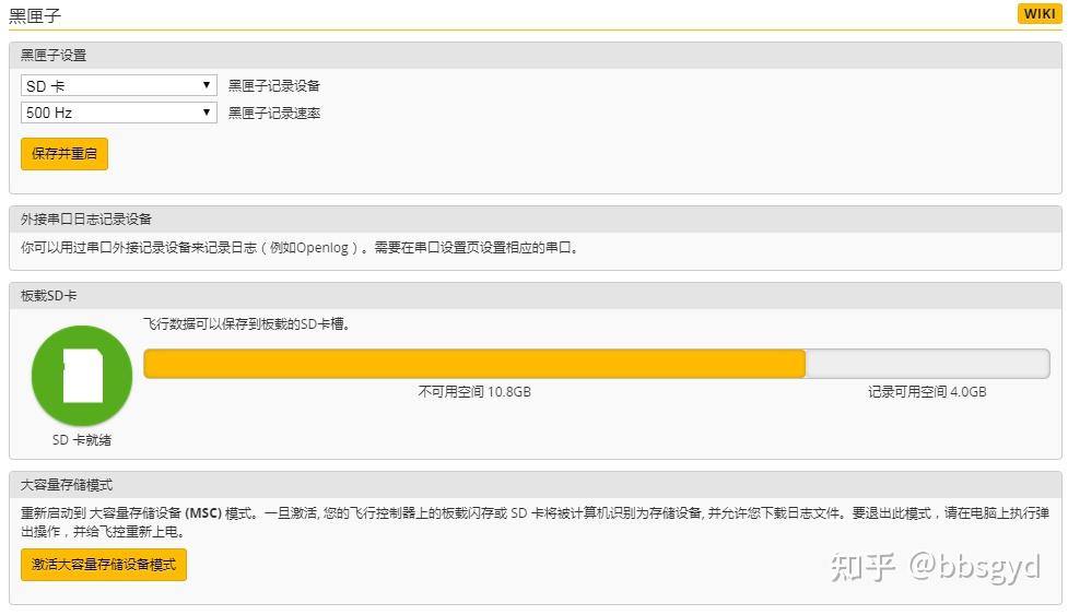
Flight control with memory card slot can be inserted into 4GB memory card
Betaflight Blackbox Explorer software is used to view flight record data and observe the vibration and noise frequencies of several axial movements of four motors and gyroscopes during flight, providing a reliable basis for flight control PID parameter adjustment. By using Blackbox software to view the flight data recorded by the flight recorder, see the waveform data of the XYZ axial of four motors and gyroscopes, analyze the vibration and noise frequencies, find the source and make improvements, and perform software filtering on interference sources that cannot be improved due to hardware factors, so that the aircraft can fly and save power. Novices can skip the content of this section and study how to use it after the subsequent capabilities are improved.
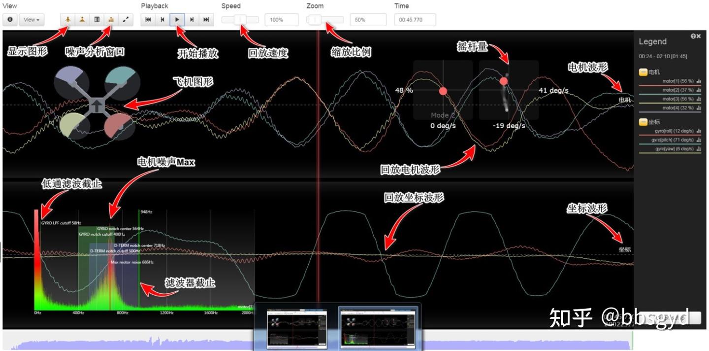
Betaflight Blackbox Explorer software to view flight record data
PID parameter settings
PID refers to “proportional”, “integral integral”, and “differential derivative”, these three items constitute the basic elements of PID.
In programming examples, error is usually used to subtract the errors obtained by real-time angles as the expected angle; iState is the sum of errors in the accumulated past time corresponding to the integral i parameter; if statement limits the iState range, and over-reproduction correction; the differential d parameter is the current pose minus the last pose, and estimates the current velocity (instantaneous velocity); the total adjustment amount is the sum of p, i, and d. (A brief understanding)
P represents the response speed of the control system. The larger the response, the faster the response. I is used to accumulate errors in the past time and correct the expected attitude value (static difference) that P cannot achieve; D strengthens the rapid response to body changes, which has a suppressive effect on P.
The PID page can set 3 different sets of data, which is convenient for switching to use different parameters during flight. To change flight parameters in the field, you can use the laptop, mobile phone, and remote control diagram to transfer and adjust parameters. Mobile phone parameters need to integrate Bluetooth wireless transceiver on the flight control board or connect to a Bluetooth device through the flight control peripheral interface.
The preset PID parameters need to be comprehensively considered according to the aircraft’s wheelbase size, motor parameters, electrostatic parameters, battery parameters, aircraft take-off weight, and propeller parameters. A set of pre-selects are set for low, medium and high P parameters; the D value is usually set for a set of corresponding P pre-selects between 25-35-55; the I value is usually set for a set of corresponding P pre-selects at 15-25-45.
P understands it as launching an expected flight action, and D strives to perform it in one go, but D may always have insufficient strength or too much force, and it is necessary to adjust the requirements of D corresponding to P; when both P and D are coordinated, use I to correct more or less deviations.
The lower the value of P, the softer the aircraft’s control movements, the higher the value, the sharper the control reactions. For example, the large-wheelbase aircraft of the F450 are lower, such as between 25-40, and the 210 crossing aircraft is generally more reasonable, and the maximum flight can reach about 85 in fancy flights.
The value of D is determined by the output capability of the motor. The greater the total power that the motor can output, the lower the value of D should be. Of course, if it is too low, the aircraft is easy to swing, the movement execution is insufficient, and the expectation posture of P is difficult to be implemented in place. If the action angle of the aircraft is large, it is easy to fall. It is usually believed that the D of the 2306 motor is between 15-35.
The value of D is too high, and the execution of the action is too strong, which makes the flight action more violent. The movement is too strong, and it is easy to perform too much. It is always difficult to control the expected value. In this way, the correction is constantly corrected back and forth, and the motor is prone to become hot and consumes power. It is more reasonable for aircraft with a large wheelbase D value between 25 and 45. The figure below is the PID parameters of the test machine using DJI 2312A, original 9450 paddle and Haoying 20A PWM electrostatic control on the F450 rack for reference.
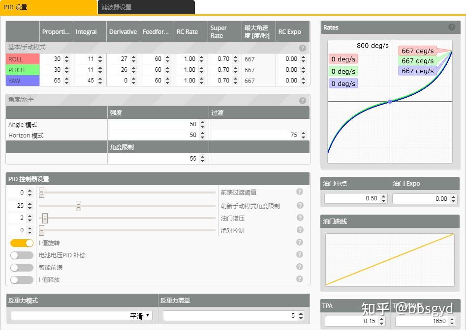
PID parameter setting page
The I value is to correct the error between the expected value P and the execution force value D. If both P and D are perfectly matched, I can be 0, which is of course difficult to achieve. Huafei and the crossing machine usually set P and D to a higher level, so the I value will also be higher, such as the 210 wheelbase crossing machine P45-65, D40-75, and I will be between 35-55. Usually, different power schemes have different parameters, so it is better to keep the motor stable during test flights and not burn.
Adjusting PID is a gradual and time-consuming task. Novice roughly sets a basic stable parameter for practice. When the control and perception ability are improved, then spend time thinking about the PID parameter settings to make the aircraft fly better. There is no need to study PID from the beginning. Because various ability conditions are not improved, it will be a waste of effort.
Setting of filter parameters
The filter is set to solve the resonance and jitter caused by hardware defects, filter out unnecessary sampling frequency intervals, calculate useful execution data, and prevent the motor from performing useless actions caused by vibration, so as to achieve the purpose of stable flight actions and unscaling of the aircraft motor and saving power.
Hardware filter: gyroscope low-pass filter, gyroscope notch filter.
Operational filter: D term low pass filter, D term notch filter, yaw low pass filter
Hardware filtering and software filtering complement each other. After hardware filtering, purer data can be handed over to the operation filtering, which can more effectively obtain the execution data. However, excessive hardware filtering will cause the missing input sampling parameters, which is not a good thing for the ultimately obtained useful data.
Hardware filters are used to filter and ignore certain vibration frequencies without sampling. How can we know which noise interference frequencies are caused by vibration? Through the Betaflight Blackbox Explorer software, view flight record data, observe some of the inherent characteristics of vibration waveform images, and set corresponding filtering parameters to obtain more ideal sampling data and hand it over to the calculator to calculate the execution data. During the operation, some vibration frequencies that cannot be filtered are added in, resulting in the occurrence of operation noise data. At this time, a certain processing is required using a computing filter.
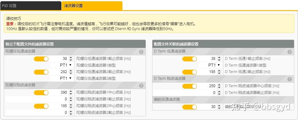
The aircraft that use all gyroscope filters must be bad
Scientific and reasonable settings of the calculation filter can make the hardware filter filter less original sampled data, and more complete original sampled data can make the final calculation results more accurate, making the motor simpler to execute and more stable flight.
The correct setting of the filter can make PID debugging more effective, and it is also the basis for PID parameter adjustment.
Hardware filter settings
The hardware filter setting of the gyroscope is based on the principle that high energy is not low. Usually, the cutoff frequency of the gyroscope low-pass filter 1 is above 100Hz (PWM electro-modulation is recommended to 150Hz). The particularly bad shaking rack and deformed paddle can be set to 50Hz, which is too low and the aircraft cannot fly. This allows the frequency below the set value to pass the sampling and enter the calculation process.
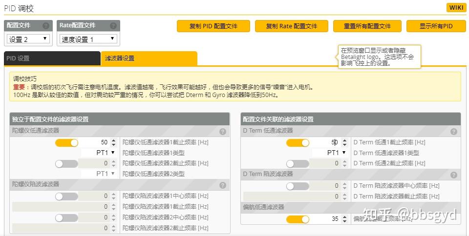
Gyroscope low pass filter settings
The center frequency of the gyroscope hardware notch filter 1 needs to be determined based on the test flight data in the flight data recorder and is accurately set according to the vibration frequency. If there is no flight record data basis, it is useless to turn it on, so it is better to turn it off.
If it is set to 50Hz or lower here, it is recommended to set the gyroscope sampling update frequency option in the Settings-System settings, and set it to 2K, which is enough. The F450 can fly well with 1K in a large wheelbase.
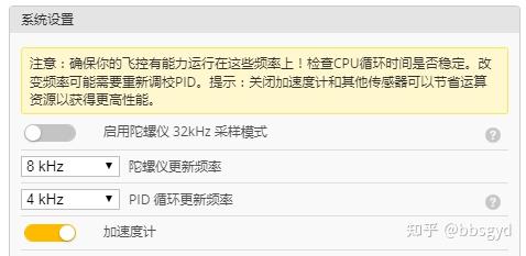
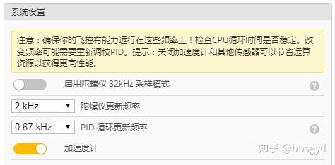
Comparison of gyroscope update frequency settings
Operation filter settings
The cutoff frequency of D term low pass 1 is usually set to 100Hz (PWM electro-modulation protocol recommends 150Hz). When the aircraft’s hardware is bad, you can also refer to the frequency of the gyroscope low pass filter 1 above to set it.
The center frequency of the D term notch filter needs to be determined based on the test flight data in the flight data recorder and is accurately set based on the vibration frequency. If it is not based on the flight record data, it is useless to turn it on, so it is better to turn it off.
The center frequency of yaw low-pass filtering is set to 100Hz. The parameters here have little impact on flights. It is possible that the settings to 25Hz will not make any significant difference (the PWM electro-modulation protocol is cautious to set these parameters, which is too low and easily out of control).
CLI command line configuration
In addition to using the options of the graphical interface to modify the flight control parameters, BF parameter adjustment can also be set using the command line, which is the CLI command line input window.
After clicking this window, if you want to return to other settings pages, the flight control will restart, so after you enter many commands, you need to enter SAVE to save it before leaving, otherwise you need to enter the command again. Many commonly used command formats and parameters can be downloaded on the official website about the CLI command line.
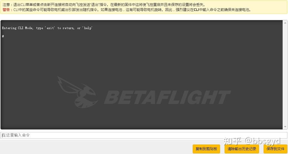
CLI command line input window
The command line can be used to set ports, interrupt numbers, define IO pins, configure LED light strips, BB rings, receiver types, PID parameters, filters, electrostatic motor parameters, etc. You can use command lines that meet flight requirements according to the adjustment requirements.
For example, in the model of the flower aircraft, you can try to enter set rc_smoothing_type = FILTER Enter, and then enter SAVE to save; the function is to activate the remote control input signal filter; the function is to remove the spikes caused by the sudden lever of the remote control, so that the motor is not that hot. Also, the parameter setting commands we used in the LED light strip setting section in the previous LED is also performed in the CLI command line window.
The hardware assembly and flight control debugging of the flight platform have been completed. One of the important things to be done in the future is the practice of flight control skills. Sharpening the knife will not delay chopping wood. Let’s start with theory.
The basics of crossing machine control
Assemble and set up the plane, go to the suburbs to find open land and stay away from the crowds! Start checking the installation direction and tightening of the propeller, check the remote control settings correctly, install the aircraft with a power battery, let the aircraft sit horizontally and let it complete self-test, put the aircraft 10 meters away from it, face the tail of the aircraft, unlock the motor, and prepare for a test flight. If you have not learned or practiced the use of a remote control, stop here and do some basic exercises.
Remote control basics
The rocker definition of the remote control: American hand, left hand rocker throttle and heading control, right hand rocker pitch and roll control, SWD switch unlocks the motor, and SWC switch switches for flight mode.
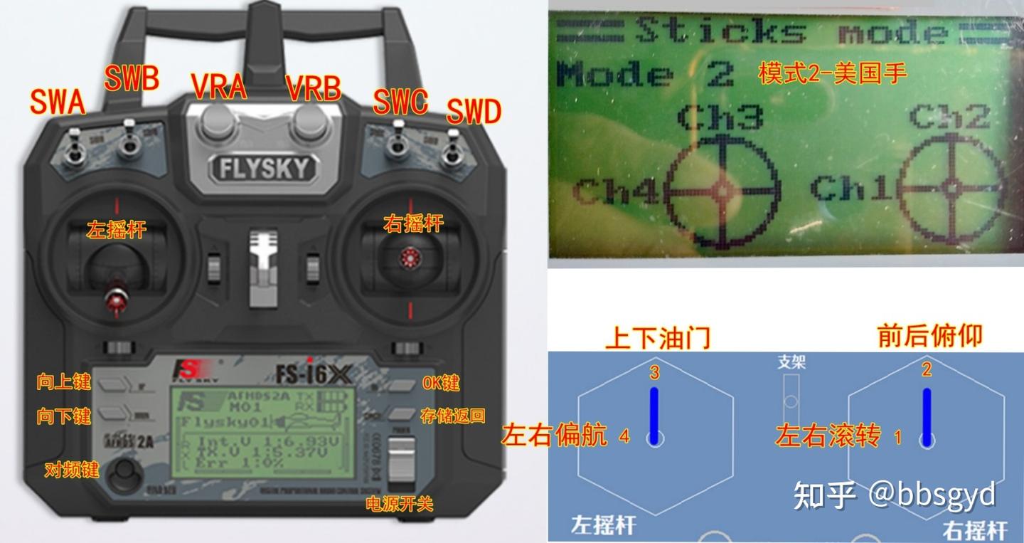
Remote control panel rocker and button definition
After understanding the definition of the joystick and buttons of the remote control, beginners need to hold the remote control, place their thumbs on the left and right rockers, and gently shake the rockers until they can control them freely and without any obstacles when they are able to control them.
The up and down of the throttle rocker passage 3 must be pulled at any time, and is used to continuously adjust the altitude of the aircraft so that the aircraft neither soars into the sky nor falls to the ground. Beginners usually do not master it well and need to practice more.
Yaw left and right rocker channel 4 is used to control the head orientation of the aircraft. Beginners usually need to face the tail so that the control direction will not be messed up, so novices generally do not shake it to change the head orientation.
The front and rear pitch channel 2 is used to control the displacement of the aircraft position toward the front of the head or rear of the tail, and it will automatically return to the center when it is released.
The left and right rolling channel 1 is used to control the displacement of the aircraft position to the left or right side of the nose. When it is released, it will automatically return to the center.
The SWC switch has three gears, and the front gear is set to self-stabilization mode. For beginners, do not try to switch to the middle and towards the rocker. That is the semi-stabilization and full manual gear. It will easily lead to a loss of control when you use it when you start.
Basic flight actions
Be familiar with the functions and operations of the remote control joystick and switch, and then practice throttle control. Push the throttle rocker upward appropriately to let the aircraft slowly leave the ground. Take off altitude about 1 meter and try to maintain the height slightly through the up and down of the throttle rocker until the aircraft can basically maintain the altitude. If the aircraft drifts, gently retract the throttle, let the aircraft land on the ground and take off again to practice taking off. Do not push the throttle lever too much during the throttle control, as it is very dangerous to do so. The exercise of hovering the plane takes a lot of time, about 1-5 hours, which varies from person to person. Don’t worry, and you need to keep your heartbeat at a normal level.
When the throttle can control the aircraft to basically hover, start using the right rocker to control the aircraft to maintain it in a certain hover position. The practice time is about 2-5 hours until the aircraft is controlled and the heartbeat is stable and does not accelerate.
When you practice the basic movement of the throttle and hover position, you can basically stabilize it. Start practicing front, back, left and right movements, and change the hover position of the aircraft, that is, pitch and roll movement control. The practice time is about 5-10 hours. This exercise requires that the final aircraft can basically maintain the same altitude when flying and stopping, and the flight trajectory is basically a straight line. After flying forward, backward, left and right, you can try to move the plane to any direction and maintain the height.
After a period of practice, these controls have become more and more proficient, and the controllability of the aircraft has become very high. Try to switch to semi-steady mode to practice. In this mode, the aircraft’s movements are significantly accelerated. When tilted to a certain angle, the aircraft may quickly rush to the ground. You must release the right-hand lever in time to let it return to the center, so that the aircraft automatically maintains a horizontal posture, and replenish the throttle to prevent the aircraft from colliding with the ground.
If you are proficient enough in semi-steady mode, fly the plane to a higher altitude and try to make a small roll. The key to controlling the small roll is: recharge the throttle, quickly pull the throttle to the left or right to the maximum, and immediately reduce the throttle to the minimum. When the aircraft turns back to the approaching horizontal posture, appropriately recharge the throttle to maintain the aircraft height. At the same time, quickly release the throttle with the right hand to let it go back to the center. At this time, there should be a fanatical heartbeat acceleration, and practice more. It is very important for a new celestial hand to pass this psychological hurdle.
When these controls are easy to handle, switch to full manual mode to try to control the hover of the aircraft. After practicing for a while, perform position movement exercises, and when you are proficient, perform rolling control exercises.
If this aircraft can be repaired and continued to be used here, it means that the user is extremely talented and deserves to advance to a professional pilot and engage in multi-rotor related work. If you can’t get the full manual mode after blowing up several units, don’t be discouraged. Fighters are also an improvement. If you haven’t blown a few hundred times, how can you see this course you have released!
Finally, install a camera and image transmission transmitter board, bring glasses, and adapt to the FPV perspective control aircraft for a period of time. With such a good foundation, you only need a little practice to do whatever action you want to fly. Your aircraft control level will be much better than scholars who start manually on FPV.
The following is the content used by the new black box parameter adjustment software added in the advanced version:
“Playing the Quadcopter” Advanced Edition of Flight Recorder and F4 Flight Control Parameter Control Methods for Waveforms
“Playing a quadcopter” series courses
Basics of use of BF Blackbox flight data recorder
Course about F405 flight control black box
Basics of use of BF Blackbox flight data recorder
Guo Yuandong, Youjiang District, Baise City, Guangxi WeChat bbsgyd 2020.05.07
When you first came into contact with open source flight control, you will be satisfied as long as you can install it and use the flight control default parameters to make the aircraft fly smoothly. Regarding the matter of adjusting parameters, it is just a quick look at the forum and search Baidu, pick some of the furs about adjusting parameters, and copy the various parameters and experiences of the masters. I feel that the plane can fly steadily, so I will no longer worry about adjusting parameters.
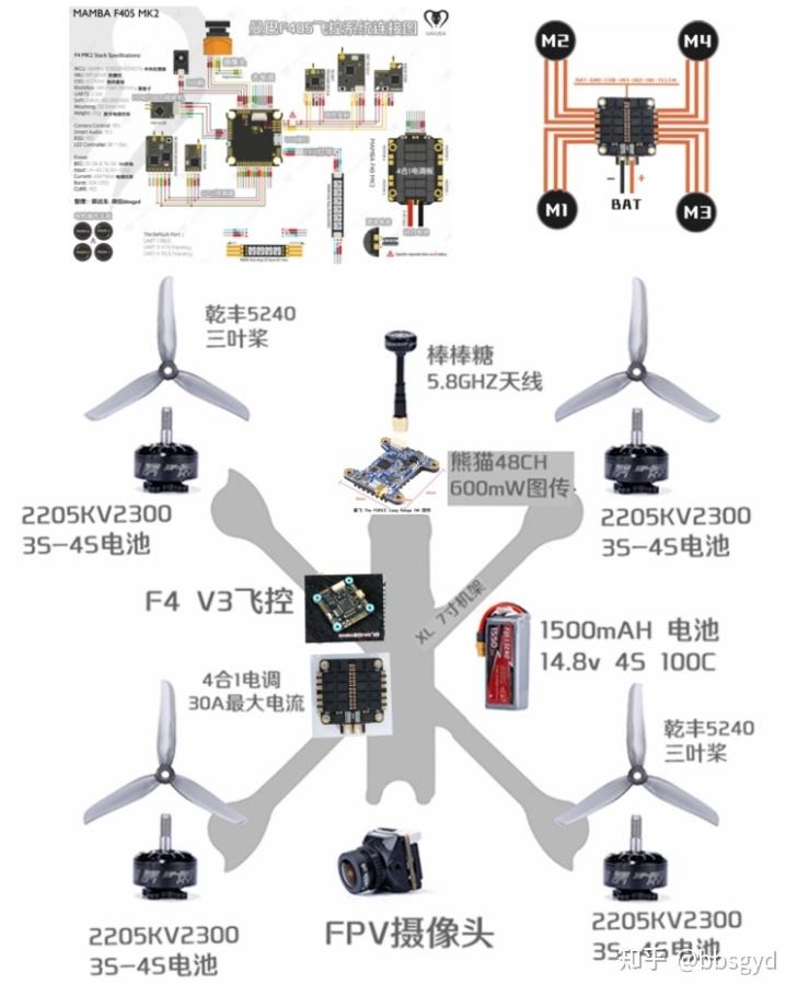
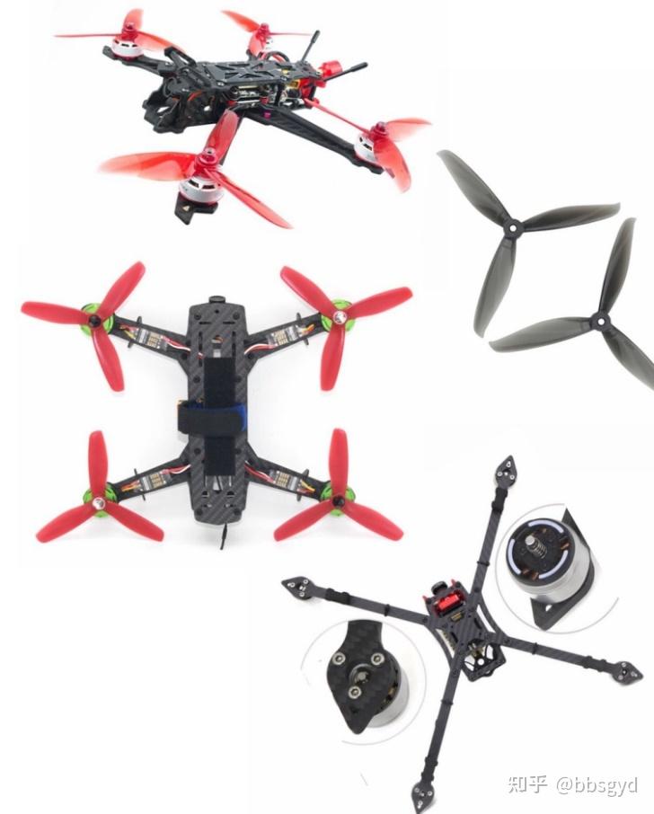
When encountering a very bad motor or a very soft rack, it is like a blind man touching an elephant. Facing the various resonances and the high temperature of the motor, we often have no patience to continue and have to give up those unpopular parts.
After many outfield flight practices, the flight control skills of multi-rotor aircraft have been gradually improved from the initial self-stabilization mode to the skilled rolling action stage of full manual mode, which put forward higher requirements for aircraft that originally felt they were flying well. After an aircraft is assembled, the hardware is basically determined. After all, this is the best solution summarized by many people. It is not easy to change it too much. To make the aircraft have good handling, PID parameter adjustment is a corner that cannot be avoided and cannot be avoided.
Perhaps 90% of open source flight control users have adapted other people’s plans and even copied the adjustment parameters. However, the slight differences in the production of the aircraft vary according to the person, material, and technology, resulting in a large difference in the vibration frequency generated by the aircraft. The original parameters cannot adapt to the aircraft. Whether to fly the same or adjust the appropriate parameters before flying again seems to be a dilemma.
Let’s first learn about F4 flight control, this small microcontroller circuit board, which integrates functional components such as the STM32F405 processor, MPU6000 six-axis gyroscope, barometer and flight recorder device. This is a complete flight controller. Firmware that writes different functions to it can make it suitable for multi-axis aircraft, triangular wings, fixed-wing aircraft, ship models, car models and other electronic devices that require attitude calculation.
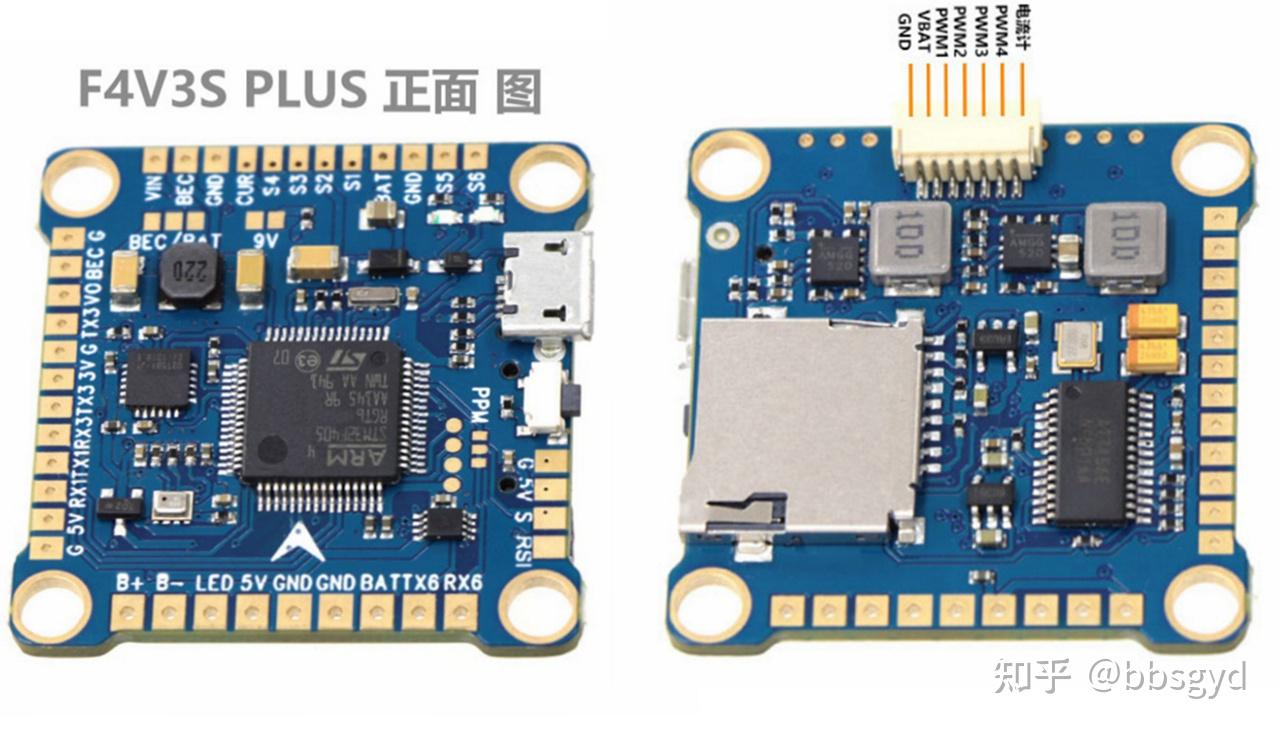
STM32F405 open source flight control diagram
This article will take the beginner to learn how to use the STM32F405 flight control flight recorder step by step, and accurately set the hardware filter and operation filter parameters on the BF ground station parameter adjustment software to filter out those annoying vibrations, avoid the noise that makes the motor hot, and make the aircraft’s handling to a higher level.
Let’s get to know the BF ground station parameter adjustment software. Its full name is Betaflight Configurator. This is a general open source flight control debugging platform software that many masters have thought about and improved. The F4 flight control described in this article uses it to set flight parameters.

BF flight control and control ground station software startup interface
There is a page in the BF settings about the flight recorder. Let’s first understand how to use it. Set a switch in the remote control channel to erase flash memory contents on the BF mode page. Wait for about 30 seconds to complete when erasing, so there is no need to use a computer to erase the data saved by the flight recorder, which will be much more convenient.
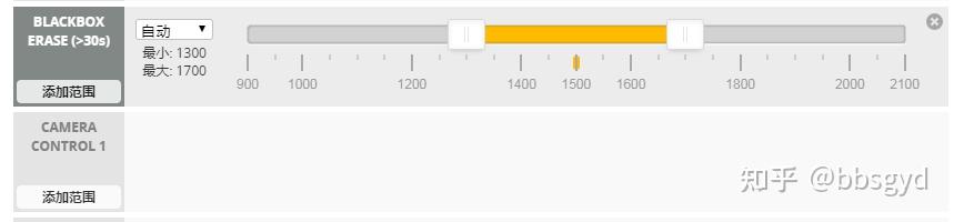
Flight recorder flash erase switch mode settings
Go to the black box page of BF, what you need to set here is the recording device “onboard flash memory” and the recording rate is “1kHz”. There is “erase flash memory” for the onboard flash memory operation, which requires a long wait.
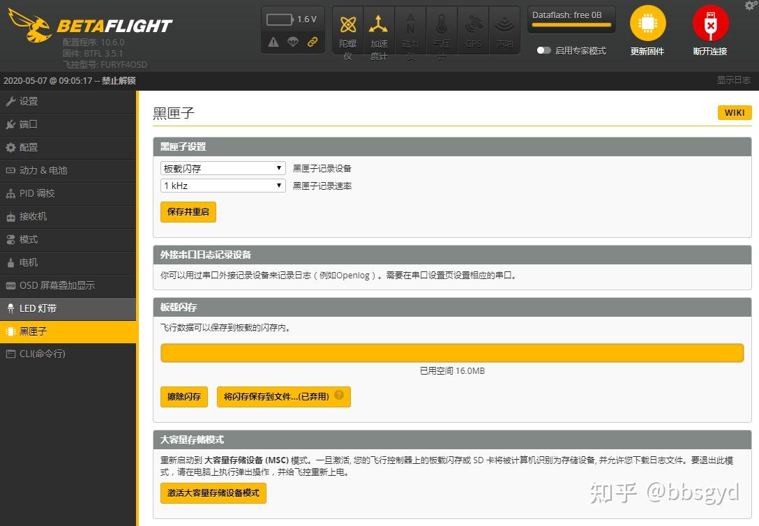
Flight recorder page for BF parameter adjustment
The above diagram is the general basis for F4 flight control board-mounted flight recorder flash memory. If the switch to format flash memory and record data is not set in BF mode, then the limited flash memory will stop recording new flight data if the flight control operating system is full; if the flash memory space is sufficient, when the motor unlocks and starts recording, the motor closes and stops recording, and automatically name the numbered flight data in sequence. The last number is the latest flight data.
On the black box page, “Save Flash to File…”, it means saving the recorded flight data to the computer and selecting the last one to save (remember which folder to save it, and open it with a viewer later). The following button “Activate the mass storage device mode” is to restart the flight control and use the flight recorder as a USB flash drive for the computer to read. The copying speed of this mode will be faster.
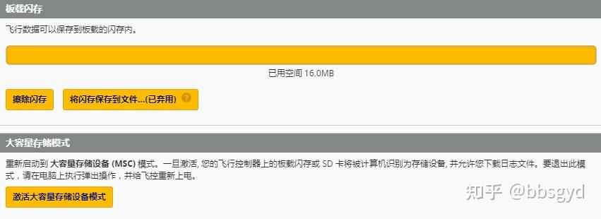
Read and save flight data in black box page
Most F4 flight controls with non-onboard flash memory have a TF slot. The firmware used generally has SD, such as betaflight_3.3.2_OMNIBUSF4SD.hex. You need to insert a TF card with a capacity of less than 4GB into the onboard TF card slot of the flight control (it will not be used if it exceeds the size). Wait until the flight control is turned on automatically and the flight control will be automatically formatted. Only after the flight control passes the self-test. If the TF card is of poor quality, it may take a long time to wait for the flight control to restart after insertion and fail to pass the self-test normally. You can try to replace the TF card with better quality. Of course, it may also be that the Flight Control’s firmware version is not compatible with some TF cards. Try to upgrade the Flight Control’s firmware to a newer version and try again. Usually, after upgrading the firmware to 4.0.0, the Flight Control starts the first time after inserting the TF card, and the time for waiting for the self-test to be completed will be much shorter.
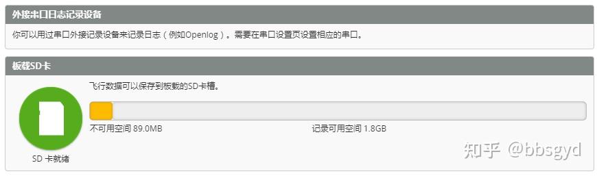
The flight control of the onboard SD card is ready to be inserted into the TF card
In the “Black Box Settings” column, I found that the recording rate cannot be set. I still cannot enable this option after repeated attempts. What should I do? In fact, there is no need to worry, the flight data will be recorded normally after the motor is unlocked.
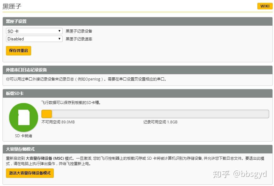
Black box ready page
After the test flight is over, the flight control connects to the computer and enters the black box page. Click the “Activate Mass Storage Device Mode” button. The flight control will disconnect from the BF ground station software. At this time, when you open “My Computer” and find that there is an extra disk in the computer. After opening it, you will see the flight record data.
The I disk is the TF card disk built-in in the SD card slot of the flight control black box flight recorder, with a capacity of 1.91GB.
Open the LOGS folder on the disk, see the neatly arranged flight record files, and copy them to the computer.
Recording files in the flight recorder disk
It is time for the flight recorder data viewer to appear. After each flight data is recorded, download it to the computer, install the Betaflight Blackbox Explorer software, run it and use it to open the flight record data, you can see the three axial data about the motor noise and the gyroscope. The filter is modified through the BF parameter adjustment software to perform motor noise and axial vibration frequency filtering parameters, so as to achieve stable flight attitude, reduce motor overheating, and save battery power consumption, and solve the problems in aircraft design and production from the software.
The download and installation of BF ground station parameter adjustment software will not be described here. This article provides a detailed introduction to the acquisition and basic use of the Betaflight Blackbox Explorer flight recorder data viewing software.
Shareware link QR code network disk sharing software folder
The software can be downloaded from the official website or other websites. Here, it provides a network disk sharing connection, including BF parameter adjustment software, flight data viewer software Betaflight Blackbox Explorer, as well as some commonly used firmware and F4 flight control drivers.
Link: https:// pan.baidu.com/s/18_4Ctg 4PlWlpOCYt-lwpVwExtraction code: v8v8.
After downloading and installing the Betaflight Blackbox Explorer flight recorder data viewing software, run the software icon on the desktop, click the Open log file/video button on the initial interface, and select the file.
Select *.BFL flight record file
In the interface that appears after the flight record data viewer software is opened, first get familiar with the functions of each block.
Through Betaflight Blackbox Explorer, you can view the interface descriptions, understand the button and graphics functions, and set the filter parameters in the BF parameter adjustment through intuitive frequency data, so that some vibration problems that are difficult to solve in system hardware design and manufacturing can be solved through software settings. How to interpret and use the above figure is a concern for everyone. Let’s introduce the usage method in detail below.
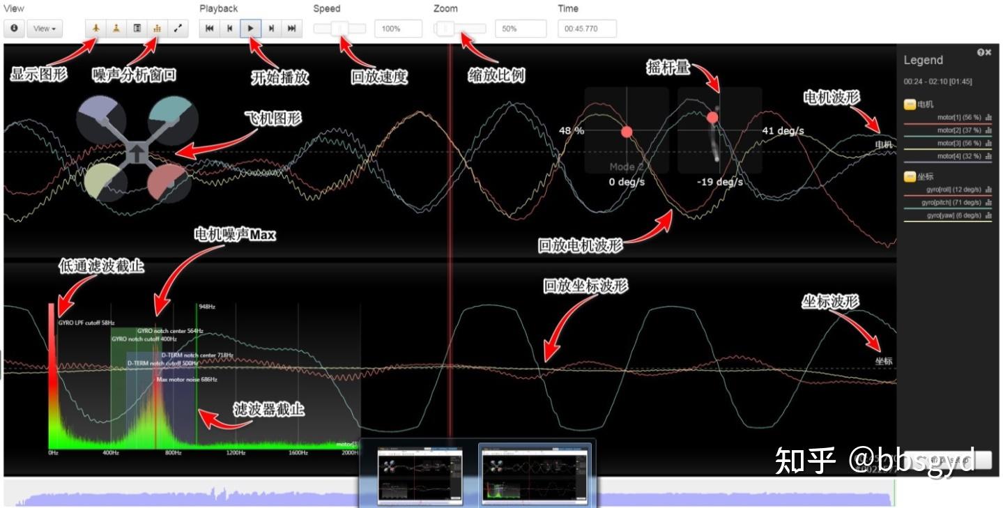
Description of the typical viewing interface of Betaflight Blackbox Explorer
Click the Open log file/video button on the main interface of Betaflight Blackbox Explorer to record data and select it. After waiting for a little, the playback interface appears. By clicking on the relevant options, the motor noise curve shown in the figure below appears. Waveforms of different colors represent different motors.
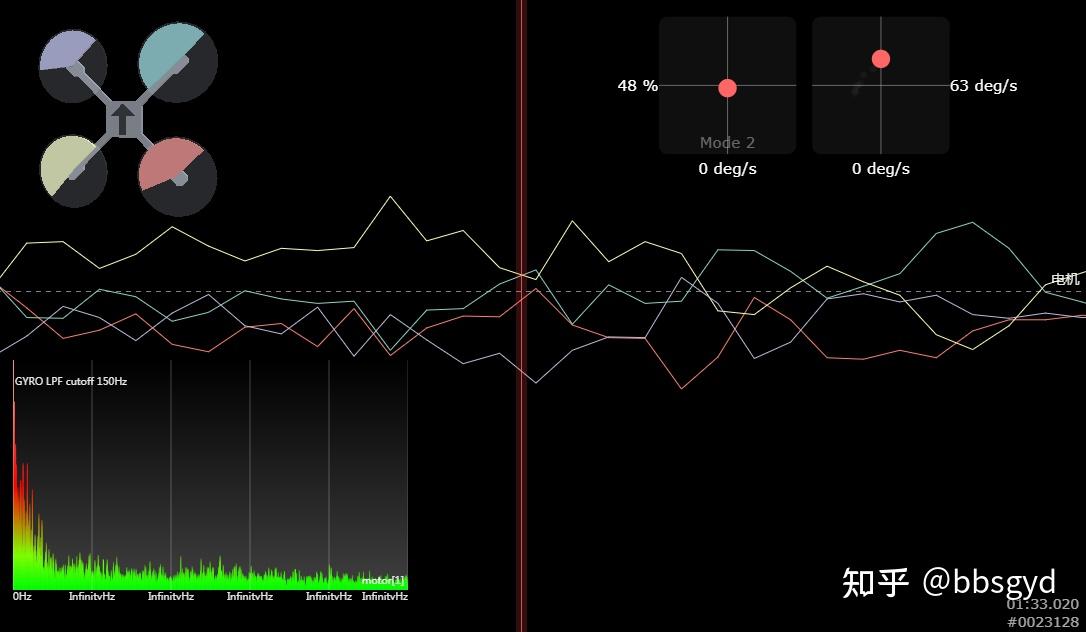
PWM electro-modulation protocol motor noise curve diagram
In the graph window, the curve charts of 4 motors, frequency observation window, aircraft attitude curve, aircraft attitude diagram, rocker quantity diagram, other curve charts that need to be displayed, etc.
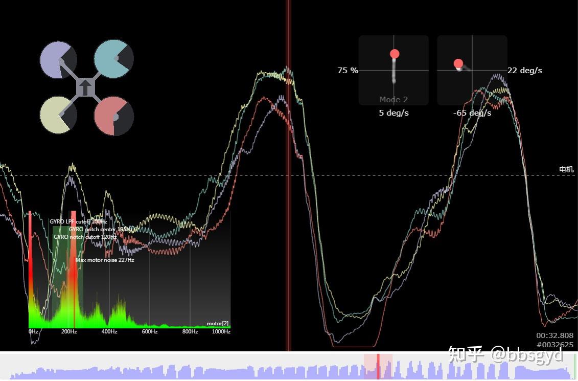
Motor noise waveform diagram under Dshot electro-modulation protocol
The toggle button allows you to view the relevant field values.
PWM signal motor Field values field values
Translation: Field values field values, loopIteration loop iteration, Raw value raw value, Decoded after decoded.
With different electro-modulation protocols, the data recorded by the flight recorder looks different during playback. Through comparison, it can be seen that the motor waveform under the PWM electro-modulation protocol is relatively rough, while the motor waveform under the Dshot electro-modulation protocol is much more delicate. For a crossover machine, using hardware that supports the Dshot electro-modulation protocol can make the flight control action more refined.
Click the Noise Analysis Window button to display it in the lower left corner, double-click any color line under the motor on the right, and then display it in full screen through the shift+A of the keyboard or click the Noise Window Maximization button.
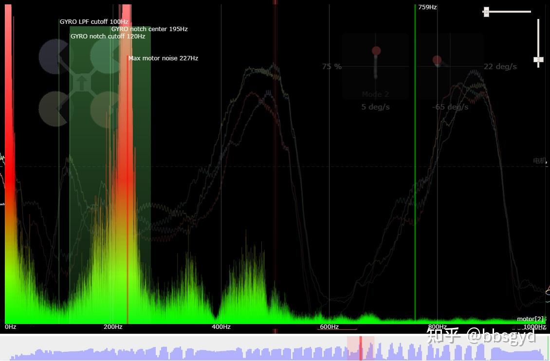
Full screen display noise graph analysis window
Through the illustration window, it can be seen that the noise of the motor is distributed between 200-240Hz. A filter is used, and the center frequency of the filter is set at 195Hz, filtering out the vibration signal of 200-240Hz. By observing the figure, record the overlapping vibration frequency data of several motors, then observe the axial vibration data, and finally set the filter parameters in BF to filter out the vibration frequency values that do not require sampling.
Click the “Graph setup” button in the lower right corner of the main interface and add “Gyros” under +Add Graph. This is the axial graph viewing interface. Through the Legend bar on the right side of the main interface, select the item to be displayed, and you can display a waveform diagram of a certain axial direction separately. The following is a waveform diagram of the axial vibration data of ROLL horizontal roll, showing that the vibration is very small, and the center frequency of the motor noise is at 639Hz. Since the vibration amplitude is relatively small, such waveforms basically do not require filtering settings in the BF parameter adjustment. Here users need to learn how to add and delete items that need to be viewed and record the vibration frequency values and intervals that need to be filtered for use in the BF filter.
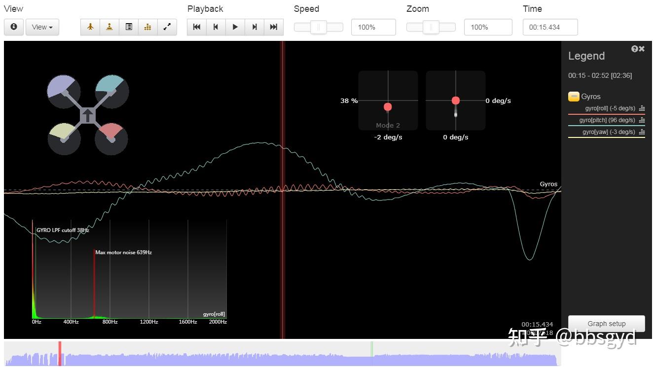
The vibration frequency of the ROLL roll is very small
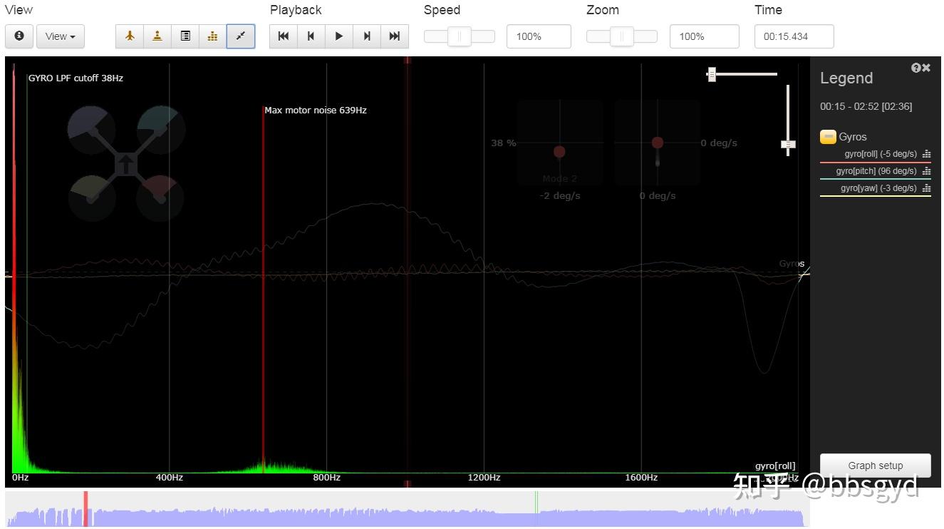
ROLL axial vibration frequency window full screen display
Under the “Graph setup” button on the main interface, there are many data windows that can be set to view in the Add Graph option.
By the way, translate the options in English: Motors motor, Gyros gyroscope axial, RC Command remote control command, PIDs integration system, PID Error, Gyro+PID roll gyroscope roll axial PID, Gyro+PID pitch gyroscope pitch axial PID, Gyro+PID yaw gyroscope yaw axial PID, Accelerometers accelerometers.
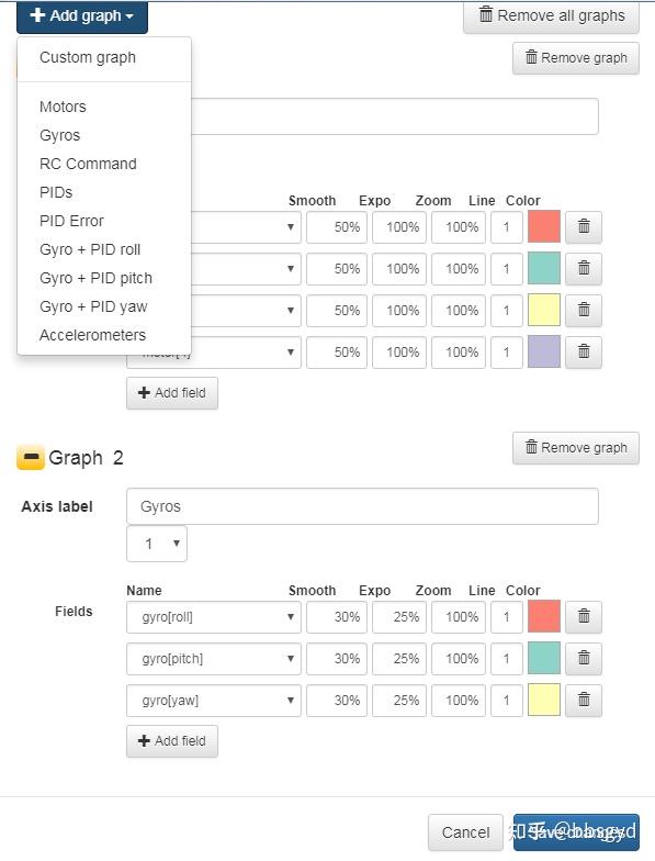
Add Graph option under the “Graph setup” button
First learn to use Motors motors and Gyros gyroscopes to analyze data axially, and continue to master and use other analysis items in future exploration and learning.
After learning to use Betaflight Blackbox Explorer software to view flight data graphics and analyze vibration range, then master the PID interface filter page of BF parameter adjustment and use the corresponding filter to filter out those vibration signal frequencies.
By recording flight data, viewing and analyzing flight data, we can obtain the frequency interval value of the more serious interference vibration. Then, in the BF ground station software, connect to the flight control, enter the filter page of PID parameter adjustment for corresponding settings, and save it after setting; try flying again, and it is necessary to correct the settings of the filter data until the aircraft is ready to fly.
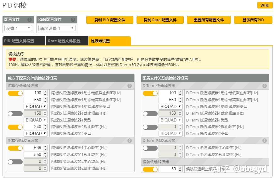
Settings of gyroscope filters and operation filters
The filter settings are as follows for the waveform parameters of the aircraft’s flight record data analysis of the above Dshot EDM protocol. If you need to know more about this, then learn and master the following content on the working principle of the filter to prepare for the use of the filter.
Setting of filter parameters
The filter is set to solve the resonance and jitter caused by hardware defects, filter out unnecessary sampling frequency intervals, calculate useful execution data, and prevent the motor from performing useless correction actions caused by vibration, so as to achieve the purpose of stable flight operations and unscaling of the aircraft motor and saving power.
The aircraft that use all gyroscope filters must be bad
Hardware filter: gyroscope low-pass filter, gyroscope notch filter.
Operational filter: D term low pass filter, D term notch filter, yaw low pass filter
Hardware filtering and operational filtering complement each other. After hardware filtering, purer data can be handed over to operational filtering, which can more effectively obtain the execution data. However, excessive hardware filtering will cause the missing input sampling parameters, which is not a good thing for the ultimately obtained useful data.
Hardware filters are used to filter and ignore certain vibration frequency sampling. How can we know which interference frequencies are caused by vibration? Betaflight Blackbox Explorer software is used to view flight record data, observe some of the inherent characteristics of vibration waveform images, and set corresponding filtering parameters to obtain more ideal sampling data and hand it over to the calculator to calculate the motor execution data. During the operation, some vibration frequencies that cannot be filtered are added in, resulting in the occurrence of operation noise data. At this time, a certain processing is required using a computing filter. Scientific and reasonable setting of operation filters can make the hardware filter filter less original sampled data, and more complete original sampled data can make the final calculation results more accurate, making the motor simpler to execute and more stable flight.
The correct setting of the filter can make PID debugging more effective, and it is also the basis for PID parameter adjustment.
Hardware filter settings
The hardware filter setting of the gyroscope is based on the principle that high energy is not low. Usually, the cutoff frequency of the gyroscope low-pass filter 1 is above 100Hz. The particularly bad shaking rack and deformed paddle can be set to 50Hz. It is too low and the aircraft cannot fly, especially the electric control using the PWM protocol. A low-pass filter allows the frequency below the set value to pass through sampling and enter the calculation process, while vibrations above the cutoff frequency setting value of the low-pass filter are no longer needed. This solves the hardware design and production process defects such as the medium and high frequency resonance caused by the jitter of the arm, such as the inability to increase the power.
Gyroscope low pass filter settings
The center frequency of the gyroscope hardware notch filter 1 needs to be determined based on the test flight data in the flight data recorder and is accurately set according to the vibration frequency. If there is no flight record data basis, it is useless to turn it on, so it is better to turn it off. The 50 parameters shown here in the figure above indicate that vibration frequencies below 50HZ will be used and sent to the operation filter. If it is set to 50Hz or lower here, it is recommended to find the gyroscope sampling update frequency option in the settings-system settings of the BF parameter adjustment software and set it to 2K. This is enough. The F450 can fly well with 1K in a large wheelbase. Of course, for a racing traverser, the 32k sampling will not be very high.
Comparison of gyroscope update frequency settings
Operation filter settings
The cutoff frequency of D term low pass 1 is usually set to 100Hz. When the aircraft’s hardware is bad, you can also refer to the frequency of the gyroscope low pass filter 1 above.
The center frequency of the D term notch filter needs to be determined based on the test flight data in the flight data recorder and is accurately set based on the vibration frequency. If it is not based on the flight record data, it is useless to turn it on, so it is better to turn it off. The settings parameters here are not a problem for flight control that supports the Dshot electrostatic control protocol. If the aircraft using the PWM electrostatic control protocol, it is recommended to set them above 150, otherwise the aircraft may lose control and cannot take off. The above parameters are set to 50 during the test. The aircraft vibrates. When the electric control continues to refuel, the throttle will be terminated and enter the idle running state. The flight control needs to restart before the corresponding throttle acceleration command will resume in this cycle.
The center frequency of yaw low-pass filtering is set to 100Hz. The parameters here have little impact on flights. It is possible that the setting to 50Hz will not make any significant difference. After setting the PID and filter parameters, perform test flight acquisition and experience the flight control status until the modification is strong and smooth and accurate.
The adjustment of the aircraft is a process of choosing between strong execution and smooth and accurate performance.
appendix
BF firmware download address
https://github.com/betaflight/b etaflight /releases
BF firmware flight control configuration file address
https://github.com/betaflight/u nicked- targets /tree/master/configs/default
BF firmware parameter adjustment ground station software address
https://github.com/betaflight/b etaflight -configurator/releases
Black box parameter adjustment software address
https://github.com/betaflight/b lackbox -log-viewer/releases
INAV firmware address
https://github.com/iNavFlight/i nav /releases
PID parameter adjustment auxiliary software PID-Analyzer address
https:// github.com/Plasmatree/P ID-Analyzer/releases
PID parameter adjustment auxiliary software PIDtoolbox address
https://github.com/bw1129/PIDto olbox /releases
BLHeli E-control firmware address V16.8, with the new Fly Control firmware on RPM filtering version
Baidu Netdisk E-Control Firmware Link: https:// pan.baidu.com/s/1BRy0na e6ad_p6mCvzY0Dyw?pwd=bzbzExtraction code: bzbz
Share address of common software for Baidu Netdisk crossing machine open source flight control
Link: https:// pan.baidu.com/s/1Uriar2 IDbPCRd_ugFKudTQ?pwd=bzbz
Extraction code: bzbz
This course was completed on Thursday, May 7, 2020. I hope it will be helpful to new scholars who have entered the open source flight control. I hope that the errors and inappropriate aspects of the article will be pointed out and corrected and shared with more people in need. Thank you!
Recommended model aircraft learning website
51 Model Network Address http://www. 5imx.com/
Moyouba website http://www. moz8.com/
The first draft was completed on 2020.05.07
New version improvement completed with 2022.08.03
If you need to make a carbon fiber rack version document, please check the author’s F360 model production document.